
Shell & Tube Heat Exchanger Calculator
Comprehensive guide for designing, rating, and sizing shell and tube heat exchangers using the Bell-Delaware method with TEMA standards.
1. Overview
The Shell & Tube Calculator performs rigorous thermal-hydraulic analysis of shell and tube heat exchangers per the Bell-Delaware method. It supports four operating modes (flooded evaporator, DX evaporator, condenser, and liquid-liquid) with full TEMA designation support. The engine calculates heat transfer coefficients with all Bell-Delaware correction factors (J_C, J_L, J_B, J_S, J_R), pressure drops on both shell and tube sides, and provides parametric GA drawings and Bill of Materials.
Key Capabilities
- Rating mode: evaluate thermal performance of a known geometry
- Sizing mode: determine optimal geometry for a target heat duty
- Bell-Delaware shell-side HTC with all correction factors
- Gnielinski / Dittus-Boelter tube-side correlations
- Two-phase correlations for evaporation and condensation
- LMTD F-correction for multi-pass configurations
- Parametric 2D GA drawing (longitudinal + transversal sections)
- Bill of Materials with weight estimation by component
- Global SI Engineering, US HVAC/IP and Refrigeration unit packs, with project-level traceability
- ASME VIII preliminary mechanical checks, NACE MR0175 screening and TEMA/API 660 data sheet
2. Getting Started: Rating vs. Sizing
The first decision you make is the calculation mode. This appears at the top of the input panel as a prominent toggle.
| Mode | When to Use | What You Provide | What You Get |
|---|---|---|---|
| RATING | You already have a heat exchanger (or a specific geometry in mind) and want to know its thermal performance | Complete geometry + fluid conditions | Q (kW), U, ΔP, velocities, effectiveness |
| SIZING | You know the required heat duty and want the calculator to find the optimal geometry | Target Q + constraints (velocity, ΔP, length, diameter limits) | Optimized shell diameter, tube count, length, baffle spacing |
Sizing Constraints: When in SIZING mode, you can define velocity limits (tube-side min/max), maximum pressure drops (shell and tube), tube length range, shell diameter range, and acceptable overdesign percentage. The solver iterates through standard shell sizes and tube configurations to find the best match.
3. Operating Modes
After choosing Rating or Sizing, select the operating mode which determines the heat transfer correlations used.
| Mode | Shell-Side | Tube-Side | Correlation |
|---|---|---|---|
| Flooded Evaporator | Refrigerant (pool boiling) | Process fluid (single-phase) | Cooper + Bell-Delaware |
| DX Evaporator | Process fluid (single-phase) | Refrigerant (flow boiling) | Shah/Gungor-Winterton + Bell-Delaware |
| Condenser | Refrigerant (film condensation) | Cooling fluid (single-phase) | Nusselt/Kern + Bell-Delaware |
| Liquid-Liquid | Hot fluid (single-phase) | Cold fluid (single-phase) | Bell-Delaware + Gnielinski |
4. Geometry Inputs
The Geometry tab defines the physical construction of the heat exchanger. All dimensional inputs support unit switching (mm/in/m).
4.1 Shell
| Parameter | Units | Description |
|---|---|---|
| Shell ID | mm, in, m | Internal diameter of the shell cylinder |
| Shell Type | — | TEMA shell type: E (one pass), F (two pass), G (split flow), H (double split), J (divided flow), K (kettle), X (crossflow) |
| Front Header | — | TEMA front header type: A (removable channel), B (bonnet), C (removable bundle), D (high pressure), N (fixed tubesheet) |
| Rear Header | — | TEMA rear header type: L/M/N (fixed tubesheet), P (outside packed), S (floating head), T (pull-through), U (U-tube), W (packed floating) |
| Shell Material | — | Carbon Steel, SS 304/316L, Duplex 2205, Super Duplex 2507, Titanium Gr.2, Inconel 625, Hastelloy C-276 and Monel 400 |
4.2 Tubes
| Parameter | Units | Description |
|---|---|---|
| Tube OD | mm | Standard sizes: 5/8" (15.875), 3/4" (19.05), 1" (25.4), 1-1/4" (31.75), 1-1/2" (38.1) |
| BWG | — | Birmingham Wire Gauge — determines wall thickness and ID |
| Tube Length | m, mm, in | Effective tube length (typical: 1.5–6.0 m) |
| Tube Pitch | mm, in | Center-to-center distance between adjacent tubes (typical: 1.25× to 1.5× OD) |
| Layout | — | Triangular 30° (best HTC), Rotated Tri 60°, Square 90° (easy cleaning), Rotated Sq 45° |
| Passes | — | Number of tube passes: 1, 2, 4, 6, or 8 |
| Tube Material | — | Copper, Carbon Steel, SS 304/316L, Duplex 2205, Super Duplex 2507, Titanium Gr.2, Cu-Ni 90/10, Inconel 625, Hastelloy C-276, Monel 400 and Admiralty Brass |
| Tube Count Override | — | Optional: force a specific tube count instead of auto-calculation from geometry |
Pitch Ratio Rule: TEMA minimum pitch is 1.25×OD. For fouling services, use 1.33×OD or higher. Square pitch (90°) is preferred when mechanical cleaning is required.
5. Fluid Inputs
The Fluids tab configures the thermal conditions on both sides. The fields shown depend on the operating mode selected.
5.1 Refrigerant (Evaporator/Condenser modes)
| Parameter | Units | Description |
|---|---|---|
| Refrigerant | — | R134a, R410A, R32, R22, R507A, R404A, R407C, R1234yf, R1234ze(E), R290, R717, R744, R600a, R1270, R123, R245fa |
| T_sat | °C, °F, K | Saturation temperature (determines operating pressure) |
| Superheat | K, °C, °F | Degree of superheat at evaporator outlet (typical: 5–10 K) |
| Subcooling | K, °C, °F | Degree of subcooling at condenser outlet (typical: 3–5 K) |
5.2 Process Fluid
| Parameter | Units | Description |
|---|---|---|
| Fluid Type | — | Water, Glycol/Water, Seawater, Thermal Oil, Light/Heavy Hydrocarbon, Amine, Brine |
| T_in | °C, °F, K | Inlet temperature of the process fluid |
| T_out (optional) | °C, °F, K | Desired outlet temperature — if omitted, calculated from energy balance |
| Mass Flow | kg/s, kg/h | Mass flow rate of the process fluid |
| Glycol % | % | Glycol concentration (0–60%) — only for Glycol/Water type |
Tip: You can specify either T_out OR Q_target (in the Target Duty field). If both are provided, Q_target takes precedence. If neither is provided, the calculator uses the full available temperature difference.
6. Baffles
Baffles are critical for shell-side heat transfer. They force the fluid to flow across the tube bundle, increasing turbulence and HTC.
| Parameter | Units | Description | Typical Range |
|---|---|---|---|
| Baffle Type | — | Single Segmental (most common), Double Segmental, Disc & Donut, Rod, No Baffle | — |
| Baffle Cut | % | Percentage of shell ID that is cut away (determines window area) | 20–35% |
| Baffle Spacing | mm, in | Center-to-center distance between baffles (TEMA: 0.2×D_s to 1.0×D_s) | 0.3–0.5 × D_s |
| Baffle Thickness | mm, in | Plate thickness of the baffle (standard: 3.175 mm / 1/8") | 3.175–6.35 mm |
| Sealing Strips | pairs | Number of sealing strip pairs to reduce bypass flow | 0–4 |
Design Rule: Baffle spacing below 0.2×D_s creates excessive pressure drop. Spacing above 1.0×D_s leads to longitudinal flow with poor HTC. The sweet spot is typically 0.3–0.5×D_s for single-phase applications.
7. Nozzles
Nozzle sizes affect inlet/outlet velocities and pressure drops. All nozzle dimensions support unit switching.
| Parameter | Units | Description |
|---|---|---|
| Shell Inlet | mm, in | Shell-side inlet nozzle internal diameter |
| Shell Outlet | mm, in | Shell-side outlet nozzle internal diameter |
| Tube Inlet | mm, in | Tube-side inlet nozzle internal diameter |
| Tube Outlet | mm, in | Tube-side outlet nozzle internal diameter |
8. Advanced Settings
The Advanced tab provides fouling resistances and calibration factors for fine-tuning the calculation.
8.1 Fouling Resistances
| Fluid | R_f (m²·K/W) | R_f (ft²·h·°F/Btu) |
|---|---|---|
| Clean water (closed loop) | 0.000088 | 0.0005 |
| Treated cooling water | 0.000176 | 0.001 |
| River water | 0.000352 | 0.002 |
| Seawater | 0.000088–0.000176 | 0.0005–0.001 |
| Light hydrocarbons | 0.000176 | 0.001 |
| Heavy hydrocarbons | 0.000352–0.000528 | 0.002–0.003 |
| Refrigerants (evaporating) | 0.000088 | 0.0005 |
| Refrigerants (condensing) | 0.000088 | 0.0005 |
8.2 Calibration Factors
| Factor | Default | Purpose |
|---|---|---|
| C_shell | 1.0 | Multiplier on shell-side HTC (use to match test data) |
| C_tube | 1.0 | Multiplier on tube-side HTC |
| C_fouling | 1.0 | Multiplier on fouling resistances |
| Rp (μm) | 1.0 | Surface roughness for nucleate boiling enhancement (Cooper correlation) |
9. Understanding Results
After clicking Calculate, results appear in the Results tab. The status bar at the bottom shows key metrics at a glance.
9.1 Performance
| Output | Description |
|---|---|
| Q (kW) | Total heat duty transferred |
| U_fouled (W/m²·K) | Overall heat transfer coefficient including fouling |
| U_clean (W/m²·K) | Overall HTC without fouling (clean condition) |
| LMTD (K) | Log Mean Temperature Difference |
| F correction | LMTD correction factor for multi-pass (1.0 = pure counterflow) |
| Effectiveness (%) | Thermal effectiveness (ε = Q_actual / Q_max) |
| NTU | Number of Transfer Units |
| Overdesign (%) | Excess area beyond minimum required (positive = safety margin) |
9.2 Bell-Delaware Correction Factors
| Factor | Physical Meaning | Typical Range |
|---|---|---|
| J_C | Baffle cut correction — accounts for flow in the window zone | 0.55–1.0 |
| J_L | Leakage correction — shell-to-baffle and tube-to-baffle clearances | 0.4–0.9 |
| J_B | Bypass correction — flow bypassing the tube bundle | 0.5–1.0 |
| J_S | Spacing correction — unequal inlet/outlet baffle spacing | 0.85–1.0 |
| J_R | Laminar flow correction — low Reynolds number effect | 0.4–1.0 |
10. Drawing Tab
After a successful calculation, the Drawing tab shows a parametric GA (General Arrangement) drawing with:
- Longitudinal section: shell, flanges, tubesheets, baffles with cut, tubes, nozzles, tie rods, TEMA headers
- Transversal section: all tubes in correct pattern, baffle cut, pass partition, OTL
- Dimensional annotations (D_s, L, pitch, D_o, baffle spacing, nozzle sizes)
- Flow arrows with different colors for shell/tube sides
- Title block with TEMA designation, model code, and performance summary
- Export to SVG/PNG via toolbar button
11. BOM & Cost Tab
The BOM tab provides a detailed weight breakdown by component:
- Shell cylinder + heads + flanges
- Tube bundle (tubes + tubesheets + tie rods)
- Internals (baffles + pass partition plates)
- Nozzles (neck + flange)
Each component shows quantity, unit weight, total weight, material specification, and key dimensions.
12. Mechanical Design and Technical Deliverables
The Advanced tab accepts shell/tube design pressure and temperature, corrosion allowance, weld-joint efficiency and head type. The mechanical panel reports preliminary ASME VIII thickness, MAWP, flange class and component status. When sour service is enabled, the NACE MR0175 panel performs a preliminary material screening using H₂S partial pressure and chlorides.
Engineering limitation: These checks support preliminary selection and consistency review; final pressure-vessel design still requires the applicable code edition, certified material allowables, detailed loads and approval by the responsible engineer.
The main PDF contains four pages. Page 2 is a dedicated TEMA/API 660-style data sheet with process conditions, construction, material basis, nozzle schedule and ASME component summary. Material IDs and catalog revision are also preserved in saved projects and EXCL files.
13. Unit System
Select a global pack—SI Engineering, US HVAC/IP or Refrigeration—in Company Settings. Every physical input still permits a local unit override. The calculator converts values to SI internally and stores the active pack, locale, precision and overrides with the project and EXCL export.
| Dimension | Available Units |
|---|---|
| Length | mm, m, in |
| Temperature | °C, °F, K |
| Delta Temperature | K, °C, °F |
| Mass Flow | kg/s, kg/h |
| Power | kW, W, TR, kcal/h, Btu/h |
| Pressure | kPa, Pa, bar, psi, atm |
| Velocity | m/s, fpm |
| Fouling Resistance | m²·K/W, ft²·h·°F/Btu |
| Surface Roughness | μm, μin |
14. Workflow Example
Here is a typical workflow for designing a new shell and tube heat exchanger:
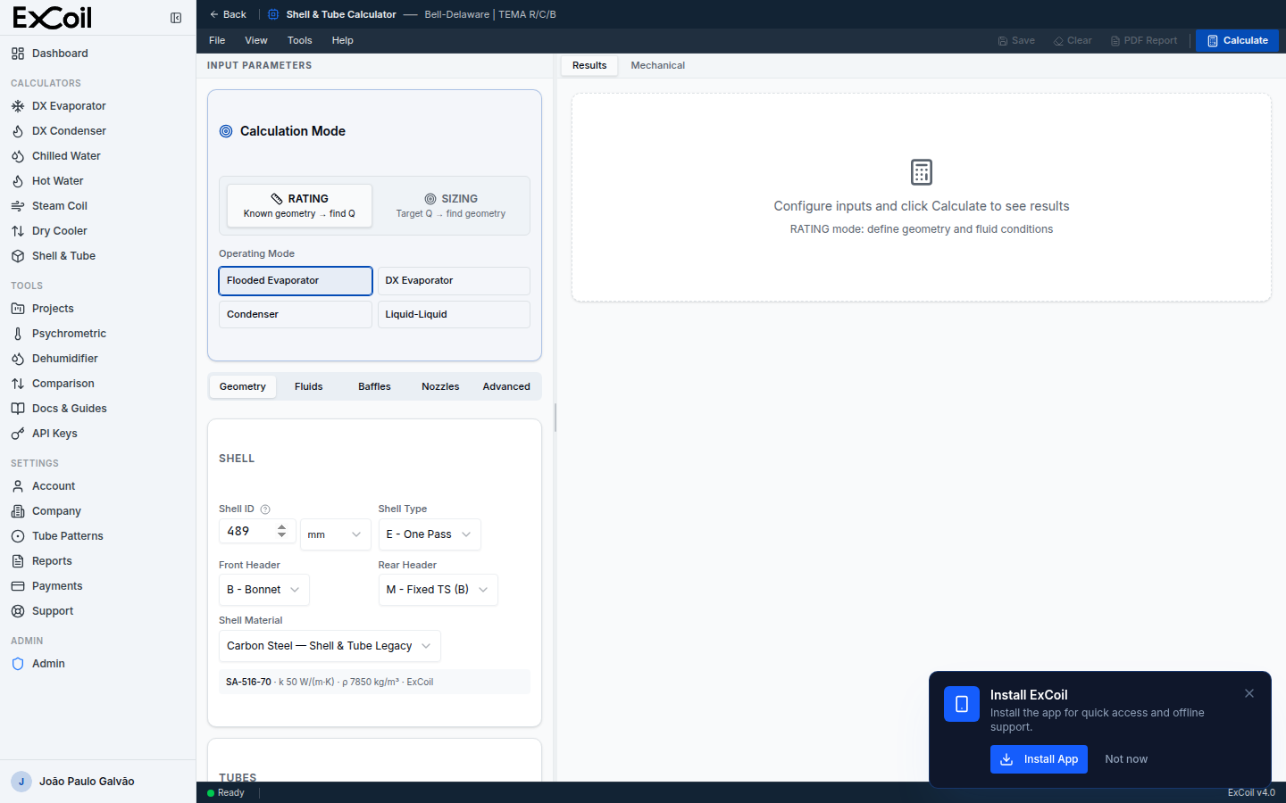
- Select SIZING mode — Enter target heat duty (e.g., 500 kW) and constraints
- Choose operating mode — e.g., Flooded Evaporator for a chiller
- Set fluid conditions — Refrigerant (R134a, T_sat=5°C, SH=5K) + Process fluid (water, 12→7°C, 24 kg/s)
- Click Calculate — The solver finds optimal geometry
- Review results — Check overdesign %, velocities, ΔP
- Switch to RATING mode — Fine-tune the geometry from sizing results
- Check Drawing tab — Verify the GA drawing looks correct
- Check BOM tab — Review weight and material breakdown
- Export PDF — Review the four-page report and the TEMA/API 660 sheet on page 2
- Save project — All inputs and results are persisted
15. TEMA Designation Reference
The TEMA designation is a three-letter code: [Front Header]-[Shell Type]-[Rear Header]. Common configurations:
| Designation | Application | Characteristics |
|---|---|---|
| BEM | General purpose, clean services | Fixed tubesheet, non-removable bundle, lowest cost |
| AES | Fouling services, refineries | Floating head, removable bundle for cleaning |
| BEU | High ΔT, thermal expansion | U-tube, handles thermal expansion, no rear tubesheet |
| AKT | Kettle reboiler | Oversized shell for vapor disengagement |
| AXL | Low ΔP condenser | Crossflow shell, very low shell-side pressure drop |
16. Troubleshooting & Warnings
| Warning | Cause | Solution |
|---|---|---|
| Tube velocity too low | Low flow rate or too many tubes | Increase passes, reduce tube count, or reduce shell diameter |
| Tube velocity too high | High flow rate or too few tubes | Reduce passes, increase shell diameter, or increase tube length |
| Shell ΔP exceeds limit | Tight baffle spacing or small shell | Increase baffle spacing, use double segmental baffles, or increase shell ID |
| F correction too low | Temperature cross or near-cross | Reduce tube passes, use F-shell (two pass), or split into multiple exchangers |
| Negative overdesign | Insufficient area for required duty | Increase tube length, shell diameter, or number of rows |
17. References
- Kern, D.Q. — Process Heat Transfer, McGraw-Hill, 1950
- Bell, K.J. — Delaware Method for Shell-Side Design, AIChE, 1963
- Taborek, J. — Heat Exchanger Design Handbook (HEDH), Hemisphere Publishing, 1983
- TEMA — Standards of the Tubular Exchanger Manufacturers Association, 10th Edition
- Shah, R.K. & Sekulić, D.P. — Fundamentals of Heat Exchanger Design, Wiley, 2003
- Cooper, M.G. — Saturation Nucleate Pool Boiling: A Simple Correlation, IChemE Symp. Series, 1984
- Gnielinski, V. — New Equations for Heat and Mass Transfer in Turbulent Pipe and Channel Flow, Int. Chem. Eng., 1976