
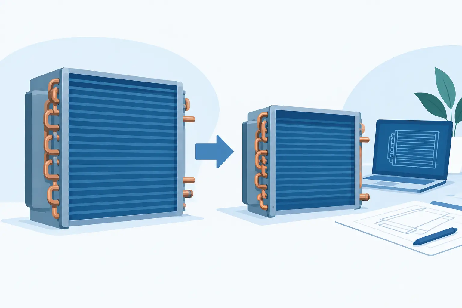
A coil can meet a nominal capacity target and still be oversized at the conditions that govern product performance. In DX equipment, the penalty may appear as low suction pressure, poor latent control, excessive compressor cycling, higher fan power, or unnecessary material cost. Knowing how to reduce coil oversizing starts with treating coil selection as a coupled refrigeration and airside problem, not a catalog-capacity exercise.
Define Oversizing at the Actual Rating Point
Oversizing is often described as selecting more capacity than the calculated load. That definition is incomplete. A DX evaporator or condenser is oversized when its effective heat-transfer surface, airflow arrangement, refrigerant circuitry, or control response produces more capacity than the system needs at its intended operating condition.
For an evaporator, the relevant condition includes entering-air dry-bulb and wet-bulb temperature, airflow, external static pressure allowance, refrigerant type, evaporating temperature, superheat, and distributor behavior. For a condenser, selection depends on ambient conditions, airflow, condensing temperature, refrigerant mass flow, subcooling requirement, and fan operating point. A coil selected from a single nominal rating can be materially wrong once these inputs shift.
The first corrective action is therefore to establish a defensible design envelope. Separate the design load from allowances for pull-down, infiltration, defrost recovery, product load variation, and future expansion. These allowances may be necessary, but they should not be hidden inside an arbitrary coil safety factor.
Start With a Better Load and Temperature Definition
A conservative load calculation does not automatically require a conservatively oversized coil. The risk is compounding margins: a load estimate includes contingency, the coil selector adds capacity, and equipment selection adds another reserve. The result is often a coil that is significantly larger than the system requires.
For comfort cooling, distinguish peak sensible load, peak latent load, and the operating hours that matter for humidity control. A larger evaporator operating at a higher evaporating temperature can improve compressor efficiency, but it may also reduce latent capacity if coil surface temperature rises too far. Conversely, lowering the evaporating temperature to force capacity can increase compressor lift and affect leaving-air conditions.
For refrigeration evaporators, define the required room temperature, product condition, design infiltration, fan heat, and defrost effects before selecting TD. A very low TD may call for a physically large coil, but this can be justified where dehydration, product quality, or room temperature stability governs. It should be an intentional process decision, not a default response to uncertainty.
Select Face Area Before Adding Rows
When capacity is short, adding rows is a common response. It is not always the best one. More rows increase refrigerant-side and airside heat-transfer area, but they also increase air pressure drop, fan energy, condensate retention potential, and sensitivity to fouling or frost.
Face area is often the more effective first variable, particularly where airside pressure drop is already limiting. Increasing face area reduces face velocity and can improve air distribution, reduce pressure drop, and provide additional capacity without forcing air through a deeper coil. The trade-off is equipment footprint and possible airflow maldistribution if the plenum, fan, or cabinet geometry is not revised with the coil.
For evaporators, face velocity also affects moisture carryover and condensate drainage. For low-temperature applications, it affects frost accumulation and time between defrosts. A selection that minimizes first cost by reducing face area can create an oversized depth requirement later in the design process.
Match Fin Geometry to the Duty
Fin density should reflect the airside environment, not merely the desired capacity per square foot. Tight fin spacing can provide compact dry-coil capacity, yet it raises pressure drop and degrades more quickly in dusty, wet, or frosting service. A coil that appears undersized in clean, dry rating conditions may become oversized in material and still underperform after modest fouling.
Wider fin spacing can reduce initial thermal performance per unit face area, but it may preserve airflow and capacity over the service interval. This is especially relevant for unit coolers, coils serving unfiltered air, and evaporators with recurring frost. The correct question is not whether a fin density produces the highest initial capacity. It is whether it meets capacity, pressure-drop, maintenance, and operating-stability requirements across the expected duty cycle.
Tube diameter, fin pattern, tube spacing, and circuit count should be evaluated together. Changing one geometric variable while leaving the others fixed can produce misleading conclusions about the source of excess capacity or pressure drop.
Use Circuiting to Control Refrigerant-Side Performance
DX coil circuiting is a primary lever for reducing unnecessary surface area. Circuit count determines refrigerant mass flux, pressure drop, distribution quality, and the progression of refrigerant quality through the coil. Poor circuit design can force a designer to add coil area to compensate for uneven feeding or excessive pressure losses.
Too few circuits may create excessive refrigerant pressure drop and lower the effective saturation temperature through the coil. Too many circuits can reduce mass flux, weaken distribution behavior, and make the coil more sensitive to unequal feeder pressure drops. Neither condition is corrected reliably by adding rows.
Circuit lengths should be reasonably balanced, with attention to vertical lift, distributor selection, feeder tubes, return bends, and refrigerant flow regime. For multi-circuit coils, verify that every circuit receives an appropriate share of flow at both full-load and reduced-load conditions. A circuit arrangement that performs well at a rating point may become unstable during low-ambient operation, compressor unloading, or variable-speed airflow.
Check Air Distribution, Not Just Rated Airflow
Coil ratings generally assume a known airflow rate distributed uniformly across the face. Actual equipment rarely achieves perfect distribution. Fan proximity, cabinet transitions, filter loading, drain pans, electric heat sections, and downstream restrictions can all shift airflow away from portions of the coil.
This matters because an oversized coil on paper can contain inactive surface area in operation. The design team may then increase total coil size to recover measured capacity, further increasing cost and pressure-drop risk. Before enlarging the coil, assess the velocity profile and the available external static pressure.
For draw-through arrangements, consider how fan placement and downstream components affect the leaving-air profile. For blow-through arrangements, examine fan discharge patterns and the distance available for flow to equalize. Coil face area, fan selection, and cabinet geometry should be developed as one airside system.
Model Off-Design Conditions Before Finalizing the Coil
A coil should not be judged solely at full-load design conditions. Part-load operation frequently determines whether a selection is genuinely oversized. Compressor staging, variable-speed compressors, electronic expansion valves, floating head pressure, changing airflow, and ambient variation all alter the balance between refrigerant flow and coil surface.
For evaporators, evaluate capacity, suction pressure, outlet superheat, air temperature, and latent performance over the expected operating map. For condensers, evaluate condensing pressure, subcooling, fan cycling or speed control, and refrigerant charge behavior at high and low ambient conditions. A coil with substantial excess area can be beneficial for seasonal efficiency, but only if the controls can maintain stable operation and the added cost is justified.
Engineering-grade thermal analysis is particularly valuable here because it resolves local coil behavior rather than treating the coil as a single capacity number. ExCoil-type analysis can help quantify the effect of circuitry, entering-air conditions, refrigerant properties, and geometry before a prototype or field test exposes a selection problem.
Apply Capacity Margin Deliberately
Some margin is appropriate. Manufacturing variation, airflow uncertainty, heat gain uncertainty, and performance degradation are real. The objective is not to eliminate margin; it is to identify its source and prevent duplication.
Document the margin applied at each stage: load calculation, coil thermal selection, fan selection, compressor capacity, and control strategy. If the load includes a 10% contingency and the coil adds another 15%, explain why both are required. In many cases, a smaller and better-circuited coil with validated airflow will provide more predictable performance than a larger coil selected with layered assumptions.
Validate With Measured Inputs and Sensitivity Studies
The final selection should include a sensitivity study around the variables most likely to change. Test airflow, entering-air condition, refrigerant mass flow, evaporating or condensing temperature, and fouling allowance. Identify whether the design remains acceptable when each input moves within a credible range.
This approach also clarifies which variable is worth improving. If a 5% airflow error has a greater effect than adding one tube row, investing effort in fan and cabinet validation may reduce oversizing more effectively than revising coil geometry. If distributor imbalance controls the result, additional surface will not solve the underlying issue.
The practical goal is a coil that delivers required capacity with stable refrigerant control, acceptable airside pressure drop, and defensible cost. When every reserve is visible and every thermal assumption is tested, coil size becomes an engineering decision rather than an accumulation of safety factors.