
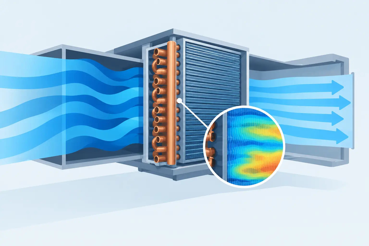
A coil can meet its rated face velocity while still operating far from its rated condition. Airflow nonuniformity coil effects arise when portions of the finned surface receive substantially different local air mass flow, temperature, or humidity conditions than the coil-average values used in a conventional rating calculation. For DX evaporators and condensers, that mismatch changes more than total capacity. It changes refrigerant distribution requirements, local heat flux, pressure drop, superheat behavior, frost risk, and the stability of the system control response.
A single average airflow value cannot describe a coil when the entering air profile is strongly skewed. Engineering-grade thermal analysis must resolve the interaction between the air-side distribution and refrigerant circuitry rather than assuming every tube row and circuit experiences the same air-side load.
Why Airflow Nonuniformity Coil Effects Matter
Air maldistribution is common in packaged equipment, air handlers, display cases, unit coolers, and condensing sections. Fan discharge swirl, poor inlet geometry, obstructions, dampers, filters, drain pans, access panels, and transitions can all create a nonuniform velocity profile. Temperature and humidity can also vary across the coil face, particularly in mixed-air applications or installations with incomplete upstream mixing.
The immediate effect is unequal air-side conductance. A high-flow region has a larger air-side heat-transfer coefficient and generally a higher local heat-capacity rate. A low-flow region has reduced air-side heat transfer and may approach very low surface loading. The resulting capacity loss is not always proportional to the airflow loss because the coil is a coupled heat exchanger. Refrigerant temperature changes along each circuit, and the location of high or low airflow relative to that circuit determines the final performance penalty.
For a DX evaporator, a high-airflow zone near a circuit inlet can produce rapid evaporation and a steep local refrigerant quality increase. If that circuit also receives a high refrigerant mass flow, it may reach superheat early while another circuit remains underfed or partially active. The distributor, feeder lengths, circuit pressure drops, and air profile then interact. A coil that appears adequately sized at uniform face velocity can deliver lower capacity and poor superheat balance in the installed assembly.
For a condenser, nonuniform airflow can leave portions of the coil with weak desuperheating, condensing, or subcooling duty. The system may respond with higher condensing pressure even if measured total airflow is near the design value. In multi-fan condensers, a failed or throttled fan is the obvious case, but less visible effects from recirculation, fan plume overlap, guard geometry, and uneven coil fouling can be equally relevant.
The Coupled Air-Side and Refrigerant-Side Response
Local face velocity is only the starting point
The air-side pressure drop relationship is nonlinear with velocity. A low-flow region does not simply surrender an equal share of flow to an adjacent high-flow region, because the coil, cabinet, fan, and bypass paths establish a system-level pressure field. A restrictive coil region, localized fouling, or a partially blocked filter can redirect air around the affected area, increasing nonuniformity further.
At the local level, air-side heat transfer commonly increases with velocity, but not linearly. Consequently, using average velocity to calculate an average air-side coefficient usually overstates performance when the velocity distribution is broad. The correct penalty depends on fin geometry, tube arrangement, row depth, wet or dry operation, and the distribution of velocity relative to refrigerant flow paths.
Circuiting determines the size of the penalty
The same air profile can produce materially different results in two coils with identical face area and nominal capacity. Circuit orientation and pass arrangement determine whether high-load and low-load regions occur early or late in a refrigerant path.
Consider an evaporator circuit entering at one side of the coil and crossing zones with markedly different face velocities. If the high-airflow zone is encountered first, much of the refrigerant can evaporate early. Downstream tubes may then operate in a superheated regime with lower refrigerant-side heat-transfer coefficients, reducing useful coil surface utilization. If the low-airflow zone occurs first, refrigerant may remain at lower quality longer and the downstream high-flow region can carry more of the latent and sensible load. Neither arrangement is universally superior. The result depends on mass flux, distributor behavior, pressure drop, expansion device control, and the entering-air psychrometric state.
Parallel circuits introduce another layer of risk. Unequal air loading changes the thermal demand of each circuit, while unequal feeder pressure drop and distributor characteristics determine the refrigerant response. A favorable refrigerant split under uniform airflow may become a poor split under an asymmetric air profile. This is why circuit-level modeling is more informative than treating the coil as one lumped heat exchanger.
Evaporator-Specific Consequences
Evaporator performance is particularly sensitive because air maldistribution can disturb both capacity and control. Low-airflow sections may run colder than intended if refrigerant distribution remains relatively high in those circuits. Where entering air is humid, those sections can accumulate frost first, increasing local resistance and creating a feedback loop: lower air flow causes more frost, and more frost causes even lower air flow.
High-airflow sections can have the opposite problem. They may impose high local load, drive rapid vaporization, and elevate circuit outlet superheat. A sensing bulb or electronic expansion valve control strategy that responds to a nonrepresentative outlet condition can overfeed or underfeed the coil as a whole. The practical symptoms may include unstable superheat, uneven leaving-air temperature, reduced latent capacity, compressor floodback risk during transients, or unexpectedly early defrost demand.
The effect is not limited to low-temperature refrigeration. Comfort cooling coils operating downstream of poorly mixed outdoor and return air can experience large temperature and humidity gradients. A coil-average entering condition may conceal a region near saturation and another region with substantially warmer, drier air. Predicting condensate formation, sensible heat ratio, and leaving-air conditions requires spatial treatment of those inlet conditions.
Condenser-Specific Consequences
In air-cooled condensers, airflow nonuniformity often appears as elevated head pressure rather than an immediately obvious capacity problem. Areas with low airflow have reduced external heat transfer, forcing a higher local refrigerant-to-air temperature difference to reject the same duty. Since refrigerant circuits are coupled through headers and system operating conditions, this local limitation can raise the required condensing temperature for the entire coil.
Subcooling distribution also matters. If downstream coil regions receive insufficient airflow, available surface for liquid subcooling can be reduced. The system may lose net refrigerating effect even when compressor operation appears normal. In heat pump outdoor coils, the situation changes again with operating mode, fan direction, and frosting behavior. A geometry that distributes air acceptably in cooling mode may not behave the same during heating-mode operation.
How to Evaluate the Problem Properly
A useful analysis begins with a realistic air-side map, not a single nominal face velocity. The map can be derived from laboratory traverses, CFD results, fan and cabinet characterization, or a measured velocity grid. It should identify the local velocity distribution and, where applicable, local entering-air dry-bulb temperature and humidity ratio.
The coil model should divide the face into sufficiently small regions and preserve the actual tube circuitry through those regions. Each segment requires local air-side conditions, fin and tube heat transfer relationships, refrigerant state progression, and pressure-drop calculations. For evaporators, the analysis should capture two-phase boiling, superheat development, and circuit-to-circuit refrigerant distribution. For condensers, it should capture desuperheating, condensation, subcooling, and refrigerant-side pressure loss.
A credible workflow compares at least three cases: an ideal uniform-airflow baseline, the expected installed distribution, and a sensitivity case representing credible degradation such as fouling, fan-speed reduction, or partial blockage. The difference between the baseline and installed case quantifies the assembly penalty. The sensitivity case helps determine whether the design has adequate margin or merely meets a nominal rating.
Measurements should also be checked for representativeness. A velocity traverse taken too close to a fan, without accounting for swirl or reverse flow, can produce misleading data. Likewise, static pressure readings alone do not define the face profile. The goal is not a visually smooth contour plot; it is an air-side input that accurately represents the thermal load seen by each coil region.
Design Responses and Trade-Offs
The first response is often to improve the air path rather than redesign the coil. Better fan-to-coil spacing, flow straightening, inlet transitions, baffles, reduced bypass leakage, and improved upstream mixing can produce a large gain without increasing coil size. However, each measure can add pressure drop, sound, cost, service complexity, or cabinet volume.
Circuiting changes can reduce sensitivity to a known airflow pattern. Designers may redistribute passes, alter circuit location, adjust feeder geometry, or modify distributor selection so that refrigerant flow better matches local thermal demand. These changes require care. A circuit arrangement optimized for one fan configuration may be less tolerant of another, and a solution that improves full-load capacity can worsen part-load control or defrost behavior.
Increasing coil face area can lower average face velocity and reduce pressure drop, but it does not automatically eliminate maldistribution. If the same cabinet geometry produces a strong low-flow corner or central jet, the larger coil may still have underutilized surface. The design target should be both adequate area and an acceptable airflow profile.
Professional HVAC&R software is most valuable here when it makes these interactions visible before hardware testing. ExCoil-style circuit-level thermal analysis supports design validation by showing where capacity, superheat, pressure drop, and surface utilization depart from the coil-average assumption.
The most useful question is not whether the fan delivers the specified total airflow. It is whether every critical refrigerant path receives the air-side load assumed by the design. Answering that question early gives the engineering team a practical basis for selecting circuitry, cabinet geometry, fan arrangement, and control margins before nonuniform airflow becomes an expensive field problem.