
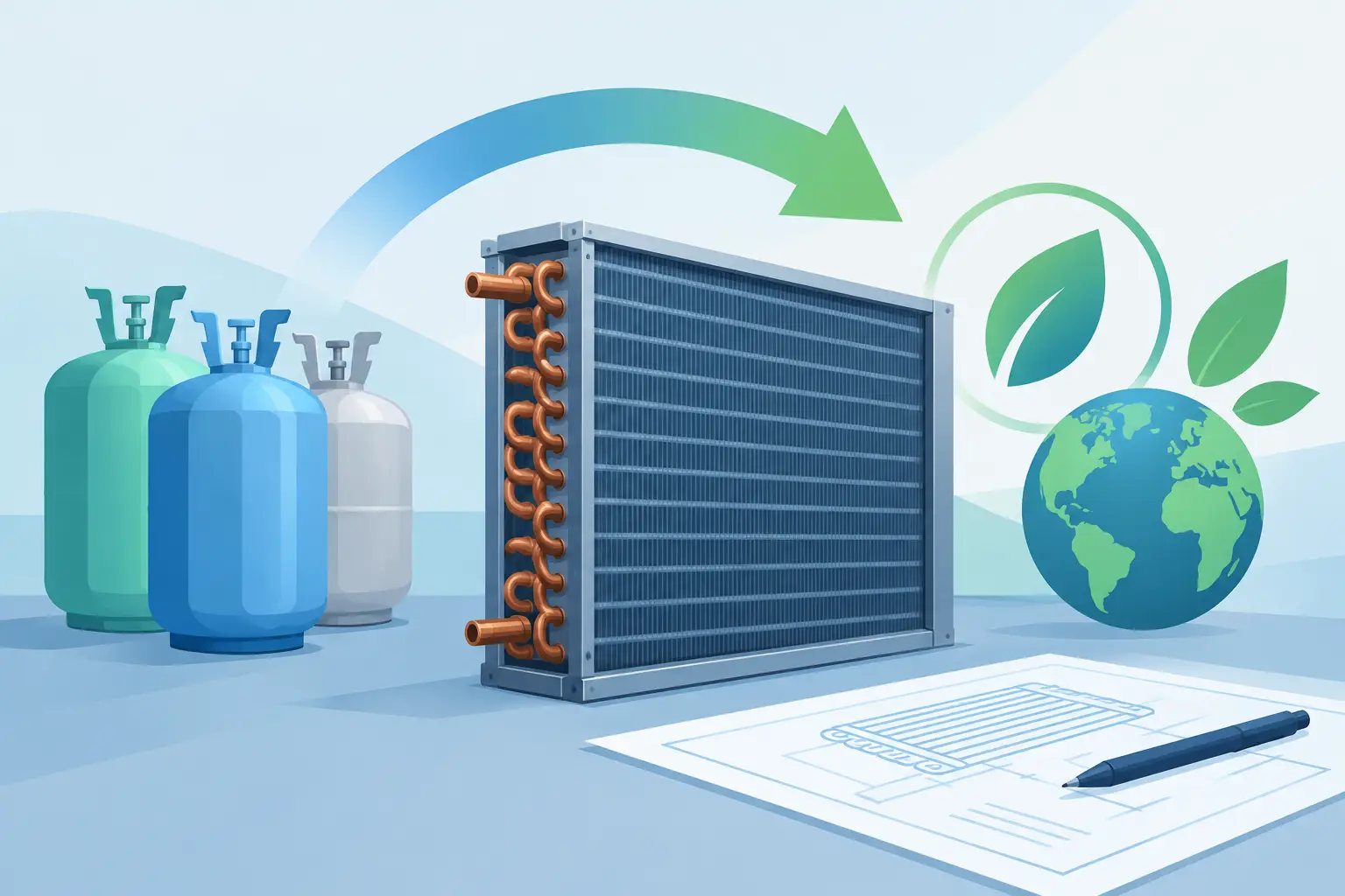
A refrigerant change can turn a proven DX coil into a different thermal system. The tubing diameter may be unchanged, but mass flux, pressure drop, saturation temperatures, discharge conditions, lubricant behavior, and safety classification may not be. Effective refrigerant transition planning treats the change as an engineering validation program, not a refrigerant selection exercise.
For OEM engineering teams, the central question is not whether a proposed refrigerant has acceptable environmental characteristics. It is whether the evaporator and condenser will deliver required capacity, efficiency, controllability, reliability, and compliance across the complete operating envelope. That answer requires component-level analysis before prototype hardware is released.
Start Refrigerant Transition Planning With the Application
A transition should begin with the equipment duty, not a nominal refrigerant comparison. Define the capacity target, entering air conditions, indoor and outdoor temperature ranges, required evaporating and condensing conditions, compressor map constraints, and defrost or low-ambient operation where applicable. A coil that appears satisfactory at one rated point can become limiting at part load, high ambient, or pull-down conditions.
This definition also needs to distinguish between a new platform and a retrofit constraint. A new product can accommodate revised circuitry, tube geometry, fin density, face area, headers, and fan selection. A legacy platform may be restricted by cabinet dimensions, existing compressor displacement, pressure-rated components, or manufacturing tooling. Those constraints determine whether optimization is realistic or whether the project is fundamentally a compromise.
Safety requirements belong in the first project definition. Many lower-GWP candidates have different flammability classifications and charge restrictions than the refrigerant they replace. The resulting system architecture may affect allowable charge, leak mitigation, electrical component selection, airflow strategy, and service procedures. These factors can change coil volume and circuiting decisions long before compliance documentation is prepared.
Do Not Compare Refrigerants by Capacity Alone
Published capacity comparisons are useful for screening, but they are not sufficient for coil design. Refrigerant performance depends on the full combination of saturation temperatures, superheat, subcooling, compressor efficiency, pressure losses, air-side conditions, and heat exchanger geometry. A replacement with similar theoretical capacity can impose materially different behavior inside the coil.
At the evaporator, examine refrigerant-side pressure drop and its effect on local saturation temperature. Excessive pressure loss reduces the effective temperature difference through the circuit, especially toward the outlet. It can also change distributor performance, circuit-to-circuit refrigerant allocation, and the available superheat margin at the compressor.
At the condenser, pressure drop affects condensing pressure, compressor lift, and system power. The transition may alter the relative length and thermal duty of desuperheating, two-phase condensation, and liquid subcooling regions. If a new refrigerant has a different pressure-temperature relationship or vapor density, an existing circuit arrangement may no longer provide the best balance between heat transfer and pressure loss.
For zeotropic blends, temperature glide adds another layer of analysis. The local refrigerant temperature changes through the two-phase region, so counterflow and crossflow arrangements must be evaluated with the actual composition and phase behavior. Assuming a single saturation temperature can misstate the local driving temperature difference and lead to inaccurate capacity predictions.
Model the Coil at Segment Level
A credible transition workflow requires more than a catalog rating or a single overall UA value. The analysis should resolve the coil by refrigerant circuit and by thermal region. For a DX evaporator, that means accounting for inlet quality or expansion-device outlet condition, two-phase boiling, vapor superheat, refrigerant-side pressure drop, and air-side temperature and humidity changes. For a condenser, it means resolving desuperheat, condensation, and subcooling with pressure loss throughout the circuit.
Segment-level modeling exposes problems that aggregate methods can conceal. A design may meet total capacity while producing excessive outlet superheat in one circuit, weak refrigerant distribution in another, or a disproportionate pressure-loss penalty in a long return bend path. These are practical risks that emerge during prototype testing as unstable control, lost capacity at off-design conditions, or inconsistent coil performance.
Engineering-grade thermal analysis should use the intended tube geometry, fin configuration, circuit layout, material selection, and airflow distribution. Air bypass, fan curve interaction, wet-coil behavior, and fouling allowance should be represented at a level appropriate to the product. A dry rated-point calculation cannot establish evaporator performance for an application where latent load and condensate management are significant.
ExCoil supports this type of component-focused evaluation by providing professional HVAC&R analysis for DX evaporators and condensers. The objective is not a simplified comparison number. It is to understand how a proposed refrigerant changes thermal performance within the actual coil architecture.
Revisit Circuitry, Headers, and Expansion Control
Refrigerant transition planning often reveals that the original circuitry is no longer the best design. Lower vapor density can require different flow areas or parallel paths to control pressure drop. A higher volumetric refrigeration effect may shift the preferred circuit count in the opposite direction. The correct decision depends on the refrigerant, capacity range, tube size, coil depth, and acceptable pressure-loss budget.
Distributor and header behavior deserve equal attention. A refrigerant change can affect inlet quality, mass flow rate, and the pressure differential available for distribution. Uneven feeding produces uneven superheat, which reduces effective heat transfer area and complicates expansion-valve control. In multicircuit evaporators, a design that looks balanced geometrically may not be balanced thermally or hydraulically.
The expansion device must be evaluated as part of the same system. Electronic expansion valves provide flexibility, but they do not correct a coil with inadequate distribution or an excessive refrigerant-side pressure drop. Confirm valve capacity, control range, pressure drop, sensing strategy, and response during startup, load changes, and low-load operation. For blends, account for the control implications of glide and potential composition changes after leakage or service.
Evaluate the Full Operating Envelope
A refrigerant transition should be judged against a matrix of operating conditions, not one nominal rating. The matrix should include minimum and maximum entering-air temperatures, part-load points, high ambient conditions, low ambient operation, and any application-specific extremes. Refrigerated cases, unit coolers, heat pumps, rooftop units, and process equipment each place different demands on the coil.
At every point, review capacity, sensible heat ratio where relevant, refrigerant pressure drop, leaving-air conditions, compressor operating limits, discharge temperature, and expansion-device authority. For condensers, include fan power and condensing-pressure control. For evaporators, include coil surface temperature, frost risk where applicable, drainage behavior, and superheat stability.
This is also where trade-offs become visible. Increasing face area may reduce air-side pressure drop and improve capacity, but it can increase cabinet size and material cost. Adding parallel circuits can lower refrigerant pressure drop, but it may make distribution more difficult. Raising fin density can increase heat transfer area, but it may reduce tolerance to fouling or frost. There is no universal coil response to a refrigerant transition.
Use Prototype Testing to Close the Model-Test Gap
Thermal modeling should direct prototype testing, not replace it. Test plans should target the conditions where the model predicts the smallest margins or the greatest sensitivity to uncertainty. Instrumentation should support a meaningful energy balance and provide enough resolution to evaluate refrigerant pressure losses, air-side temperatures, airflow, superheat, subcooling, and circuit behavior.
When measured results differ from predictions, separate model inputs from model structure. Verify actual tube wall thickness, fin geometry, circuit connections, charge, airflow, fan operating point, and sensor placement before changing heat-transfer correlations. A disciplined correlation process improves confidence in the current transition and creates a more reliable baseline for future platforms.
Production variation should also be considered before final release. Small changes in tube expansion quality, fin contact, distributor assembly, brazed-joint geometry, or fan performance can affect margins that looked adequate in a laboratory prototype. Designs with narrow thermal or pressure-drop margins are more likely to create field variability.
Build a Decision Record That Engineering Can Reuse
The final deliverable should be more than a selected refrigerant and a revised bill of materials. Document the operating envelope, coil model assumptions, calculated pressure-drop budgets, circuiting rationale, safety constraints, prototype correlation results, and remaining risks. This record allows product engineering, manufacturing, compliance, and service teams to work from the same technical basis.
A refrigerant transition is successful when the coil design has been proven against the conditions the equipment will actually encounter, not merely shown to work at a single rating point. Treat the heat exchanger as an active part of the transition strategy, and the project will produce decisions that remain defensible when the first prototypes reach the test stand.