
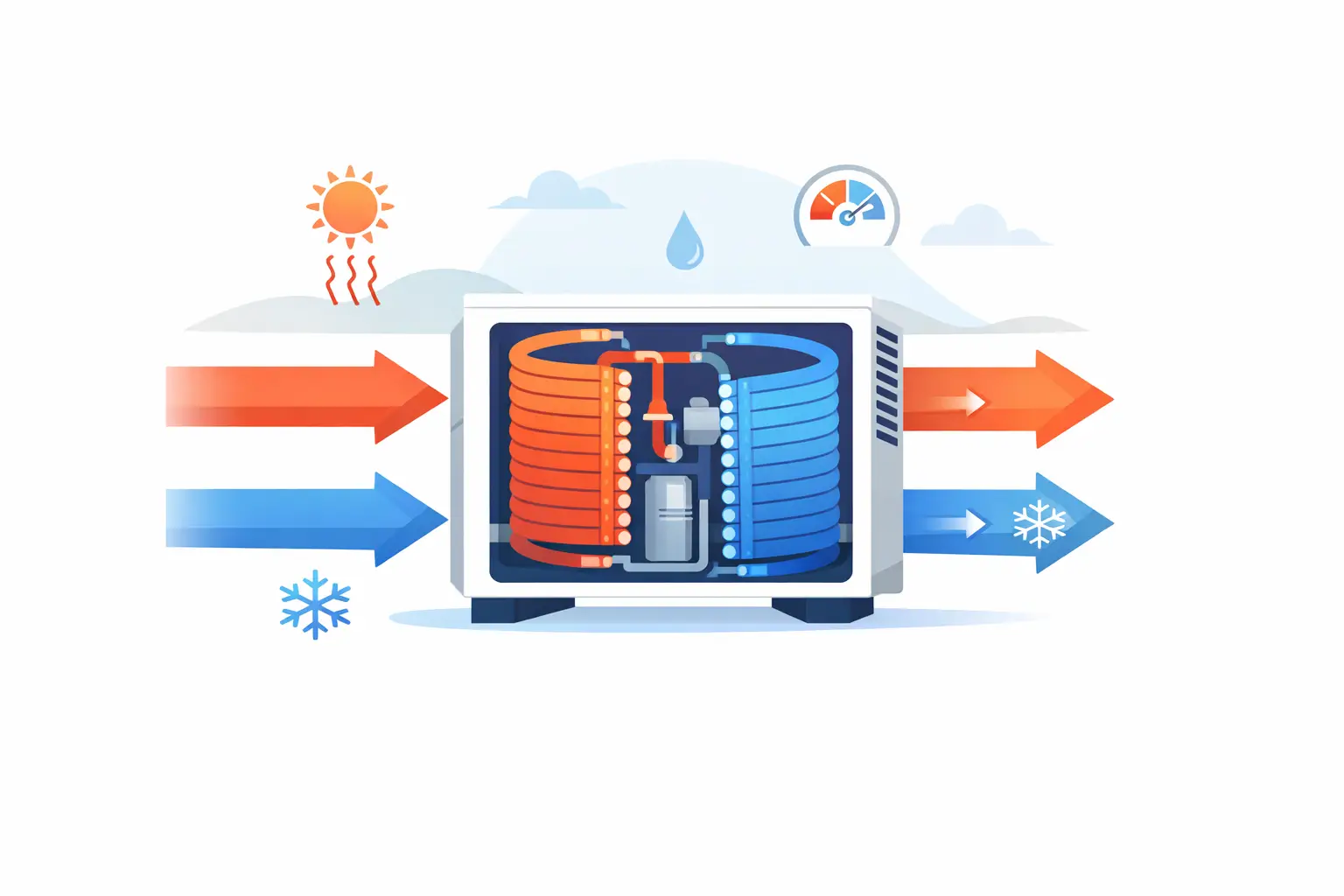
A nominal tonnage label does not define coil performance. A 3-ton heat pump coil can produce materially different capacity, sensible heat ratio, refrigerant pressure drop, and compressor operating conditions when airflow, circuiting, fin density, or entering air state changes. This heat pump coil example uses a representative air-to-air DX coil to show the inputs and checks required for an engineering-grade result.
The purpose is not to establish a universal coil selection. It is to show the calculation logic behind a performance point and identify where simplified capacity estimates create design risk.
Heat pump coil example: define the operating point
Consider a nominal 36,000 Btu/h residential or light-commercial heat pump operating in cooling mode. The indoor coil is acting as a DX evaporator at the selected condition. The outdoor section, compressor map, expansion device behavior, and line-set losses are outside the coil model boundary, but their effects must be represented through refrigerant inlet conditions and pressure constraints.
For this example, assume an R-410A system with 1,200 cfm of indoor airflow. Entering air is 80°F dry-bulb and 67°F wet-bulb, representative of a cooling rating condition. The coil has a 24-inch face height, 28-inch face length, three tube rows, aluminum plate fins, copper tubes, and six refrigerant circuits. Fin spacing is 14 fins per inch.
The initial refrigerant-side assumptions are a 45°F evaporating saturation temperature, 8°F evaporator outlet superheat, and a refrigerant distribution that is reasonably balanced across all circuits. These are starting conditions, not fixed facts. A coil model must iterate the local heat transfer and pressure-drop behavior until the air-side and refrigerant-side energy balances converge.
At 1,200 cfm, the face velocity is approximately 257 ft/min. That is generally workable for a comfort-cooling coil, but face velocity alone is not a selection criterion. The relevant result is the combination of air-side pressure drop, moisture removal, fin surface temperature, and refrigerant circuit pressure loss.
Establish the air-side load
The air-side calculation begins with psychrometric state points. At 80°F dry-bulb and 67°F wet-bulb, entering-air enthalpy is approximately 31.2 Btu/lb of dry air. A realistic evaporator solution may produce leaving air near 56°F dry-bulb with a substantially lower humidity ratio.
If the calculated leaving-air enthalpy is 24.5 Btu/lb of dry air and the dry-air mass flow is approximately 5,400 lb/h, the total air-side capacity is:
`Qtotal = ma × (hin - hout)`
`Qtotal = 5,400 lb/h × (31.2 - 24.5) Btu/lb`
`Qtotal = 36,180 Btu/h`
This result is close to the nominal 3-ton target, but total capacity is only one output. The leaving dry-bulb temperature also determines the sensible portion. Using the common air-side approximation:
`Qsensible = 1.08 × cfm × (Tin - Tout)`
`Qsensible = 1.08 × 1,200 × (80 - 56)`
`Qsensible = 31,100 Btu/h`
The implied latent capacity is about 5,100 Btu/h, and the sensible heat ratio is approximately 0.86. That split may be acceptable for a dry sensible-dominant application, but it may be inadequate for a location or occupancy profile with a higher latent load. A nominally correct total capacity can therefore still be the wrong coil.
The calculated leaving state must also be physically consistent with the coil surface condition. If the model predicts substantial dehumidification while the effective surface temperature remains above the entering-air dew point, the result is not credible. Condensate formation begins where local fin and tube surfaces fall below dew point, and the wet portion of the coil changes both heat transfer and air-side resistance.
Solve the refrigerant-side balance
For the same operating point, refrigerant mass flow must carry the air-side load. If the refrigerant enthalpy rise through the evaporator is 13 Btu/lb, a 36,180 Btu/h load requires roughly 2,780 lb/h of refrigerant flow:
`mref = Qtotal / (houtlet - hinlet)`
`mref = 36,180 / 13`
`mref = 2,780 lb/h`
A detailed model does more than apply one average enthalpy difference. It divides the coil into control volumes and evaluates local refrigerant state, two-phase heat transfer coefficient, air temperature, humidity ratio, fin efficiency, and pressure drop. The refrigerant does not remain at one saturation temperature from inlet to outlet. Frictional, acceleration, and bend losses reduce pressure along the circuit, which lowers the local saturation temperature and changes the temperature driving force.
Assume the model predicts a total evaporator refrigerant pressure drop equivalent to 0.7 psi. That may appear small, but the impact depends on refrigerant, saturation condition, circuit length, and compressor operating margin. Excessive pressure drop can reduce capacity and shift superheat control behavior. Conversely, shortening circuits too aggressively can raise refrigerant mass flux, increase distributor sensitivity, and worsen maldistribution.
For this geometry, six circuits may be reasonable at the stated airflow and load. It would not automatically be reasonable at lower evaporating temperatures, a different refrigerant, or a coil with additional rows. Circuit count is a thermal and hydraulic decision, not merely a manufacturing convention.
Check the pressure-drop and wet-coil penalties
At the example condition, a calculated wet-coil air-side pressure drop near 0.18 in. wg may be acceptable. The acceptable limit depends on the available indoor fan static pressure and the complete air path, including filters, ducts, grilles, electric heat sections, and accessories. If the design fan cannot maintain 1,200 cfm at the installed external static pressure, the coil will not operate at the modeled air flow.
That matters because reduced airflow changes nearly every coil output. Total capacity may decline, sensible capacity declines more sharply, latent fraction can increase, suction temperature changes, and the coil may become more susceptible to freeze-up. A 10 percent airflow shortfall is not a minor field detail when the design has little margin.
Fin spacing introduces another trade-off. Moving from 14 to 16 fins per inch may add surface area and improve clean-coil capacity under some conditions. It also raises air-side pressure drop and can accelerate fouling sensitivity. For applications with contaminated return air, higher fin density may increase the gap between laboratory performance and installed performance. The best geometry depends on the operating envelope and maintenance assumptions, not the peak rating point alone.
Reverse the coil for heating mode
A heat pump coil example is incomplete if it evaluates only cooling. In heating mode, the outdoor coil becomes the DX evaporator and operates at lower saturation temperatures, often with frost accumulation. The indoor coil becomes the condenser, where refrigerant-side pressure drop, desuperheating, condensation, and subcooling must be evaluated under a different set of constraints.
Suppose the outdoor condition is 47°F dry-bulb and 43°F wet-bulb. A frost-free heating calculation may predict 32,000 to 34,000 Btu/h of delivered indoor capacity for the same basic coil family, depending on compressor mass flow and indoor airflow. That result should not be treated as seasonally available capacity. As outdoor coil surface temperatures fall below freezing, frost adds thermal resistance and restricts air passages. Airflow, evaporating temperature, and capacity deteriorate between defrost events.
A practical heating analysis therefore needs assumptions for frost initiation, frost mass accumulation, air-side degradation, defrost control logic, and recovery time. These effects can dominate low-ambient performance. A coil that meets a steady-state 47°F heating target may still produce poor seasonal behavior if it requires frequent defrost or experiences severe air-side blockage at lower ambient conditions.
The indoor condenser must also be checked for discharge-temperature and subcooling implications. Increasing indoor airflow can improve condensing heat transfer and reduce condensing temperature, but only within the fan and acoustic limits of the equipment. Reducing indoor airflow may raise supply-air temperature while imposing a compressor penalty. There is no isolated coil optimization when the coil is part of a reversible refrigerant circuit.
What this example reveals about design validation
The main value of the example is not the 36,180 Btu/h result. It is the chain of dependencies behind it. Capacity depends on entering psychrometrics, airflow distribution, fin-and-tube geometry, circuit arrangement, refrigerant state, pressure drop, and the wet-surface solution. In heating mode, frost introduces another variable that cannot be represented credibly by a fixed clean-coil UA value.
For OEM development, a useful model should report more than total capacity. Engineers need sensible and latent capacity, leaving-air state, air-side pressure drop, refrigerant pressure drop, refrigerant charge estimate where applicable, circuit outlet conditions, and local temperature behavior. Those outputs support decisions about geometry, distributors, expansion devices, fan selection, compressor envelope, and rating risk.
ExCoil supports this type of engineering-grade DX evaporator and condenser analysis by treating the coil as a coupled thermal and hydraulic component rather than a single capacity multiplier.
Before releasing a coil design, test the example across the actual operating envelope: high and low airflow, dry and humid entering air, minimum and maximum refrigerant mass flow, and heating conditions that include frost exposure. The design that looks strongest at one rating point is not always the design with the lowest performance risk in equipment operation.