
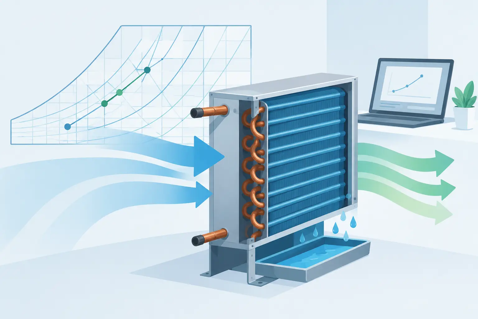
A coil can satisfy the required total capacity and still fail the application if it leaves too much moisture in the air stream, produces an unrealistic leaving dry-bulb temperature, or reaches the required duty only at an impractical air pressure drop. A reliable guide to psychrometric coil modeling therefore starts with the air state, not just a nominal tonnage rating. For DX evaporators, the air-side process must also remain consistent with refrigerant-side temperature glide, circuitry, distributor behavior, and local surface temperatures.
Psychrometric modeling converts a coil selection from a single capacity value into a defined thermodynamic process. It establishes what enters the coil, how heat and moisture are removed, what leaves the coil, and whether the result is physically credible at the intended operating condition. That distinction matters during equipment development, design validation, and troubleshooting when catalog ratings cannot represent the actual entering air, airflow, or refrigerant condition.
Guide to Psychrometric Coil Modeling: Define the Air State
Every air-side calculation begins with two independent properties and the operating pressure. Dry-bulb temperature plus relative humidity is familiar, but dry-bulb temperature plus humidity ratio or dew point is generally more useful for engineering work. Relative humidity changes substantially with temperature even when moisture content does not. Treating it as a conserved variable leads to incorrect latent-load calculations.
At the entering condition, establish dry-bulb temperature, humidity ratio, enthalpy, wet-bulb temperature, dew point, and barometric pressure. Standard atmospheric pressure is acceptable for an early comparison, but altitude or facility pressurization should be included when the model supports it. Moist-air density and specific volume affect volumetric airflow conversion and therefore face velocity.
Airflow requires the same discipline. Specify whether the stated value is actual cfm at the coil inlet, standard cfm, or mass flow rate. A coil model operating on air mass flow should not silently treat standard cfm as actual coil-inlet cfm. The resulting error can alter face velocity, air-side heat-transfer coefficient, pressure drop, and leaving condition at the same time.
The basic air-side energy balance is:
\[ Q_{total} = \dot m_{da}(h_{in} - h_{out}) \]
where \(\dot m_{da}\) is dry-air mass flow and \(h\) is moist-air enthalpy. Moisture removal follows from:
\[ \dot m_w = \dot m_{da}(W_{in} - W_{out}) \]
where \(W\) is humidity ratio. Sensible and latent capacities should be derived from these state changes rather than inferred from a fixed sensible heat ratio. SHR is a result of the coil operating point, not a universal coil characteristic.
Determine Whether the Coil Is Dry, Wet, or Part-Wet
The central question in psychrometric coil analysis is whether the coil surface is below the entering-air dew point. If it is not, the coil transfers sensible heat only. If the surface is below dew point, condensation occurs and the leaving air moves toward saturation at an effective coil surface temperature. Many real coils operate in a part-wet condition, particularly at light latent load, elevated evaporating temperature, low face velocity, or across circuits with nonuniform refrigerant distribution.
A fully wet-coil assumption can overpredict dehumidification when only part of the fin surface is below dew point. Conversely, a dry-coil model will miss condensate formation and substantially understate latent capacity once surface temperatures cross the dew-point threshold. The transition is not merely a psychrometric chart detail. It affects total capacity, SHR, condensate rate, and the downstream space humidity prediction.
For DX evaporators, local refrigerant temperature changes along the circuit. The air first encounters a coil region that may have a different effective surface temperature than later rows. Refrigerant superheat, pressure drop, circuitry, and distribution quality can all produce nonuniform wetting. A useful engineering model resolves the coil into sections or control volumes rather than imposing one average refrigerant temperature across the complete face area.
Use Apparatus Dew Point and Bypass Factor Carefully
For preliminary analysis, the apparatus dew point (ADP) and bypass factor (BF) method remains useful. The ADP is the saturated air condition that represents the effective coil surface temperature. The idealized leaving state lies on the straight process line between entering air and ADP.
For dry-bulb temperature, bypass factor is commonly expressed as:
\[ BF = \frac{T_{out} - T_{ADP}}{T_{in} - T_{ADP}} \]
The same conceptual relationship can be applied to enthalpy and humidity ratio for a fully wet coil. A lower bypass factor indicates closer approach to the effective surface condition. More face area, lower face velocity, and stronger air-side heat transfer generally reduce BF, although the refrigerant-side condition can dominate the result in a DX coil.
BF is valuable for communicating an air-side process, but it is not a substitute for a physical coil model. It embeds several effects into a single parameter: fin efficiency, row depth, velocity distribution, wet-surface heat and mass transfer, and surface-temperature variation. A fixed BF should not be extrapolated indiscriminately across airflow, entering humidity, fin spacing, or evaporating temperature.
This is particularly relevant when a coil must meet both sensible and latent targets. Two coils with similar total capacity may have different ADP values and bypass factors, producing materially different leaving humidity ratios. If humidity control is the design objective, total capacity alone is an incomplete selection criterion.
Couple the Air Side to Refrigerant-Side Physics
Psychrometric output becomes engineering-grade when it is coupled to refrigerant-side thermal analysis. The refrigerant saturation temperature, superheat profile, mass flow rate, pressure drop, tube geometry, circuit arrangement, and heat-transfer correlations determine the local wall temperature available to cool and dehumidify the air.
For an evaporator, an assumed constant suction saturation temperature may be adequate for a first-pass load estimate. It is less defensible for final design validation. Refrigerant pressure drop reduces local saturation temperature, while superheat can raise tube-wall temperature in the outlet region. Distributor maldistribution can leave portions of the coil underfed or overfed. Each condition changes the local wetness and air-side process.
The same coupling principle applies to condensers, although the psychrometric mechanism differs. Air crossing a condenser normally experiences sensible heating with no moisture removal. Still, entering-air density, actual airflow, and heat rejection determine leaving dry-bulb temperature and fan-system interaction. In applications where surface temperature falls below local dew point during transient or unusual operating conditions, condensation behavior may also need consideration.
A sectional model supports these interactions by calculating local air and refrigerant states through successive coil elements. It can represent counterflow or crossflow effects, circuit-dependent refrigerant distribution, and progressive changes in air enthalpy and humidity ratio. This requires more input data and better correlations, but it avoids forcing a complex coil into a single average temperature difference.
Check Pressure Drop and Condensate as Design Outputs
Thermal capacity cannot be evaluated independently from air pressure drop. A deeper coil, tighter fin spacing, or higher face velocity may improve heat transfer, yet it can also increase external static pressure enough to reduce delivered airflow in the installed system. If airflow falls, both sensible and latent performance change. Model the coil with the fan operating point or, at minimum, evaluate performance over the expected airflow range.
Wet-coil pressure drop deserves separate attention. Condensate retained on fins can alter the effective flow area and increase air-side resistance. Fin geometry, hydrophilic coating, tube orientation, drain-pan design, and face velocity influence drainage. A model that predicts a favorable leaving humidity ratio but ignores water management may not reflect stable field performance.
Condensate rate is also a practical validation output. Compare the predicted value from the humidity-ratio balance with measured drain flow where test conditions allow. Significant disagreement can point to errors in airflow, humidity measurement, air bypass, or unaccounted water carryover.
Validate the Model Against Measured States
A credible psychrometric coil model should be calibrated and checked against measured entering and leaving air states, airflow, refrigerant pressures, and refrigerant temperatures. Measurement quality matters. A relative-humidity sensor placed too close to a wet coil face, a poorly mixed leaving-air traverse, or an uncorrected airflow station can create apparent model error that is actually a test setup problem.
Start validation with conservation checks. The air-side total load from enthalpy difference should be reasonably consistent with the refrigerant-side load after accounting for fan heat, cabinet heat gain, and measurement uncertainty. The moisture balance should agree with collected condensate over a sufficiently long and stable test interval. Then compare leaving dry-bulb temperature, humidity ratio, pressure drop, and refrigerant outlet condition rather than relying on capacity alone.
When deviations remain, adjust only parameters with a physical basis. Airflow distribution, contact area, refrigerant distribution, correlation selection, and thermal losses are legitimate candidates. Repeatedly changing an arbitrary bypass factor until capacity matches may conceal the mechanism responsible for the discrepancy.
Use the Model to Make Better Coil Decisions
Psychrometric coil modeling is most useful when it informs decisions before hardware is committed. It can identify whether an added row primarily improves sensible capacity, whether lower fin density reduces fan power at an acceptable capacity penalty, or whether a lower evaporating temperature is necessary to meet a leaving dew-point target. The correct choice depends on the application: comfort cooling, process dehumidification, low-temperature refrigeration, and heat-pump operation place different value on capacity, SHR, pressure drop, and refrigerant charge.
Professional HVAC&R software such as ExCoil is most effective when the input conditions and validation data are treated with the same rigor as the thermal model. Define the air state precisely, resolve wet-coil behavior where it matters, and keep the refrigerant and air-side calculations coupled. The resulting model becomes more than a rating calculation: it becomes a defensible basis for coil design and performance decisions.