
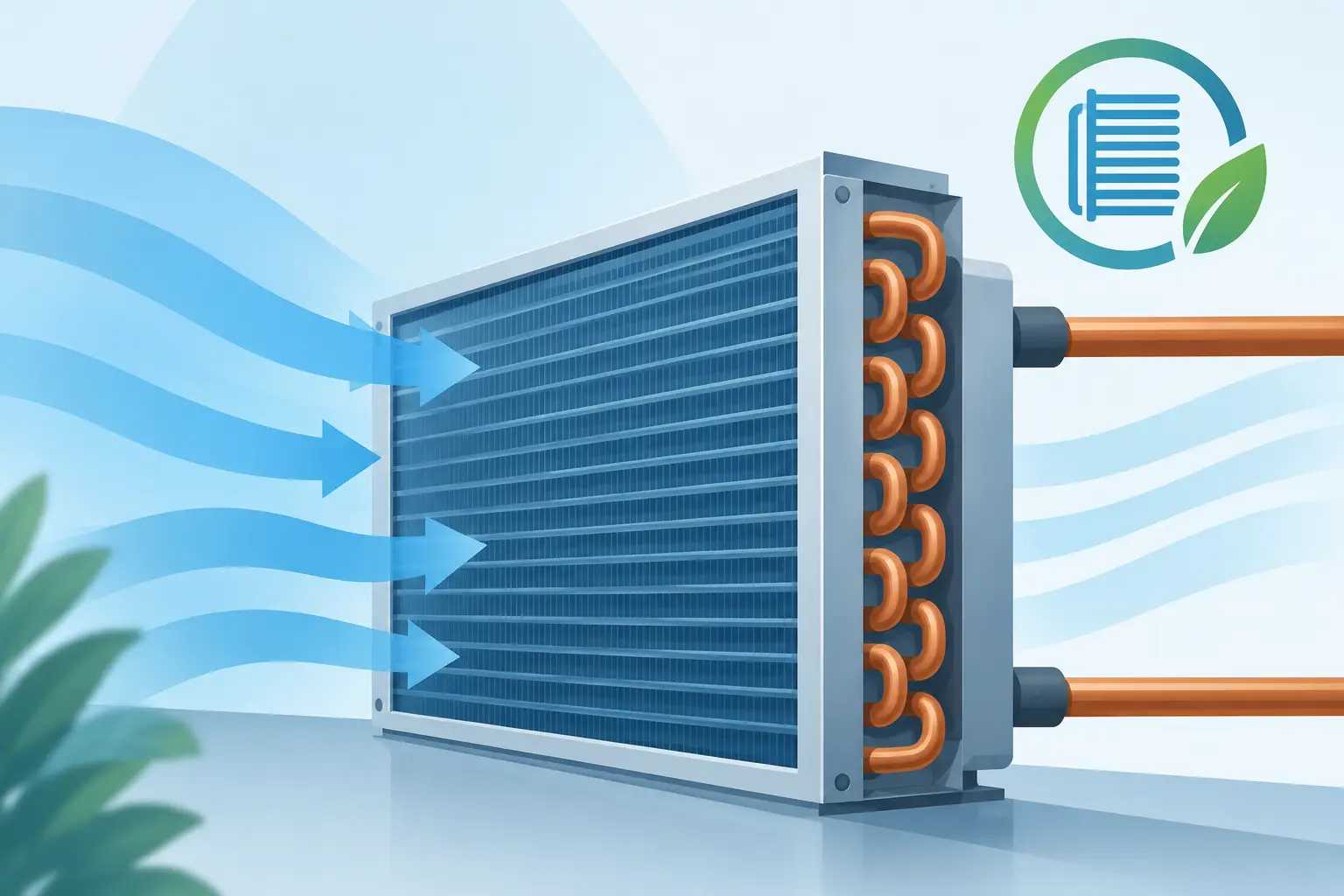
A coil can have substantial nominal airside area and still deliver less heat transfer than its geometry suggests. Fin efficiency explains that difference. It quantifies how much of a fin’s available surface area performs relative to an ideal fin held entirely at the tube-wall temperature. For DX evaporators and condensers, this is not a minor correction factor. It directly affects capacity prediction, face-area selection, circuitry decisions, fan power trade-offs, and confidence in modeled performance.
What Fin Efficiency Represents
A fin exists because bare refrigerant tubing does not provide enough external surface area for practical air-to-refrigerant heat exchange. The fin conducts heat away from the tube, creating a larger area for convection to or from the air stream. However, temperature falls along the fin as distance from the tube increases. The fin collar is near the tube-wall temperature, while regions near the fin tip move closer to local air temperature.
Fin efficiency, commonly represented by ηf, is the ratio of actual heat transfer from a fin to the heat transfer that would occur if every point on that fin remained at base temperature:
ηf = actual fin heat transfer / ideal fin heat transfer
An efficiency of 1.0 would mean no temperature drop along the fin. Real HVAC&R coil fins always operate below that value. The engineering question is not whether efficiency is perfect, but whether the selected fin geometry, material, and operating conditions produce the required thermal performance at an acceptable airside pressure drop and manufacturing cost.
This distinction matters because fin area is often a dominant portion of total external coil area. Treating all fin area as equally active overstates coil conductance. A thermal model must account for the temperature distribution through the fin, not merely add the projected area of fins to tube surface area.
The Variables That Control Fin Efficiency
Fin efficiency is governed by the balance between conduction within the fin and convection from its exposed surfaces. High thermal conductivity and a short conduction path favor efficiency. High airside heat transfer coefficients and long, thin fins increase the temperature gradient through the material and reduce it.
Fin material and thickness
Aluminum is widely used because its thermal conductivity, weight, formability, and cost are appropriate for many refrigeration and air-conditioning coils. Copper fins can provide higher conduction performance but introduce material-cost and manufacturing considerations. Coated materials require separate evaluation because coating thickness and conductivity can add thermal resistance, particularly where corrosion protection is substantial.
Increasing fin thickness generally improves fin efficiency by reducing conduction resistance. It also increases material use, coil weight, and potentially the frontal-area blockage associated with the selected geometry. Thickness should therefore be treated as a design variable, not an automatic improvement. A thicker fin with unchanged pitch may improve thermal performance, but the value of that improvement depends on the coil’s controlling resistance.
Fin height and tube spacing
The farther a point lies from the tube, the greater the conduction path required to bring it toward tube-wall temperature. Tall fins, large tube row spacing, and broad unsupported regions can lower fin efficiency. This is especially relevant in coils with large transverse tube pitch or geometries that place significant fin area far from tube collars.
Tube pattern changes can improve or reduce the effective conduction path. Staggered arrangements may enhance airside heat transfer and disrupt boundary-layer development, but they also create a more complex temperature field across the fin. The resulting coil performance cannot be determined from fin efficiency alone. It must be evaluated with the associated airside heat transfer coefficient, pressure drop, and surface-area distribution.
Airside heat transfer coefficient
Higher air velocity, louvered fin geometry, and more aggressive surface enhancement tend to raise the airside heat transfer coefficient. That improves convection potential, but it also lowers fin efficiency because the fin must conduct more heat to support the stronger local convection rate.
This is not a contradiction. A lower fin efficiency does not necessarily mean a lower-capacity coil. A more aggressive fin can produce greater total heat transfer even as its efficiency declines. The correct measure is the resulting airside conductance and overall coil capacity, considered together with fan power, noise, frost behavior, and allowable pressure drop.
Fin profile and surface enhancement
Plain, wavy, slit, louvered, and other enhanced fin patterns do not behave as simple flat plates. Louvers alter local flow direction and boundary-layer development. Slits and interruptions shorten effective conduction paths in some regions while increasing exposed edges and changing local heat transfer. Collar geometry also affects both conduction into the fin and contact quality at the tube-to-fin interface.
For this reason, simplified straight-fin equations are useful for preliminary insight but are not sufficient for final coil design validation. Correlations and models must represent the actual fin type and airside operating regime.
Fin Efficiency Is Not Overall Surface Efficiency
Fin efficiency applies only to fin area. A coil also includes exposed tube area, which is not subject to the same extended-surface temperature gradient. For coil calculations, engineers commonly use overall surface efficiency, often written as ηo:
ηo = 1 - (Af / Ao) × (1 - ηf)
where Af is fin area and Ao is total external area, including fin and exposed tube surface. Overall surface efficiency is the more useful quantity when calculating airside UA because it weights fin efficiency by the fraction of the coil area that is actually finned.
A coil with modest fin efficiency can still have a high overall surface efficiency if exposed tube area is significant. Conversely, a tightly finned coil can be more sensitive to fin-efficiency assumptions because a larger portion of its total area depends on heat conduction through the fin.
Confusing these two terms can produce avoidable errors in predicted capacity. It can also obscure whether a design change affects conductive performance within the fin, convective performance at the air surface, or both.
Why Operating Condition Changes Matter
Fin efficiency is not a fixed property printed on a coil drawing. It changes with airside heat transfer coefficient, which changes with airflow rate, air density, fin surface condition, and geometry. A coil evaluated at rated airflow may behave differently at reduced fan speed, dirty-filter conditions, altitude, or variable-speed operation.
DX evaporators add further complexity. As the refrigerant evaporates through the circuitry, tube-wall temperature can vary by circuit and along each tube path. Air temperature and humidity also change through the coil depth. The fin does not operate at a single uniform base temperature or a single uniform air temperature. Local thermal analysis is therefore preferable to applying one average fin efficiency across the entire coil when performance accuracy matters.
Condensers have a similarly nonuniform profile. Refrigerant desuperheating, condensation, and subcooling create different tube-wall temperatures in different regions. Air warming through the coil shifts the local driving temperature difference. A model that resolves refrigerant-side states, tube-to-fin conduction, and airside conditions can identify where added surface area remains productive and where geometry is producing diminishing returns.
Wet, Frosted, and Fouled Coil Considerations
Dry-surface fin efficiency is not automatically valid for evaporator conditions with condensate or frost. A water film can alter local heat transfer and may bridge fin passages. Frost adds thermal resistance, restricts airflow, changes fin geometry, and can create highly nonuniform air distribution. Under these conditions, nominal clean-coil fin efficiency is only part of the thermal picture.
Fouling and corrosion also deserve attention. Dust accumulation may lower the effective airside coefficient while increasing pressure drop. Corrosion can reduce fin thickness, degrade fin-to-tube contact, or change surface characteristics. Depending on the failure mode, the apparent effect on fin efficiency may be smaller than the effect on airflow or contact resistance. A useful analysis separates these mechanisms rather than assigning all degradation to a single correction factor.
Applying Fin Efficiency in Coil Design
A practical design workflow begins with the required duty, entering-air condition, refrigerant, allowable airside pressure drop, available face area, and circuiting concept. Fin efficiency should then be calculated as part of the airside thermal resistance model, using geometry and airside correlations appropriate to the selected fin pattern.
The value becomes most useful when compared across alternatives. Consider a denser fin pitch, a taller fin, or a more aggressive louver pattern. Each may add surface area or raise the airside coefficient, yet each may also affect fin efficiency, pressure drop, drainage, cleanability, and frost tolerance. The preferred design is the one that meets capacity and operating requirements across the intended envelope, not the one with the highest calculated fin efficiency in isolation.
Engineering-grade thermal analysis software such as ExCoil supports this evaluation by treating fin performance as part of the coupled coil problem rather than as a detached textbook value. That approach helps engineers validate whether a proposed geometry produces useful conductance under actual refrigerant and airside conditions.
For coil designers, fin efficiency is best viewed as a measure of how effectively added metal is being used. When it is evaluated with local airside conditions, tube-wall temperatures, and pressure-drop constraints, it becomes a practical basis for selecting geometry that performs predictably beyond the rating point.