
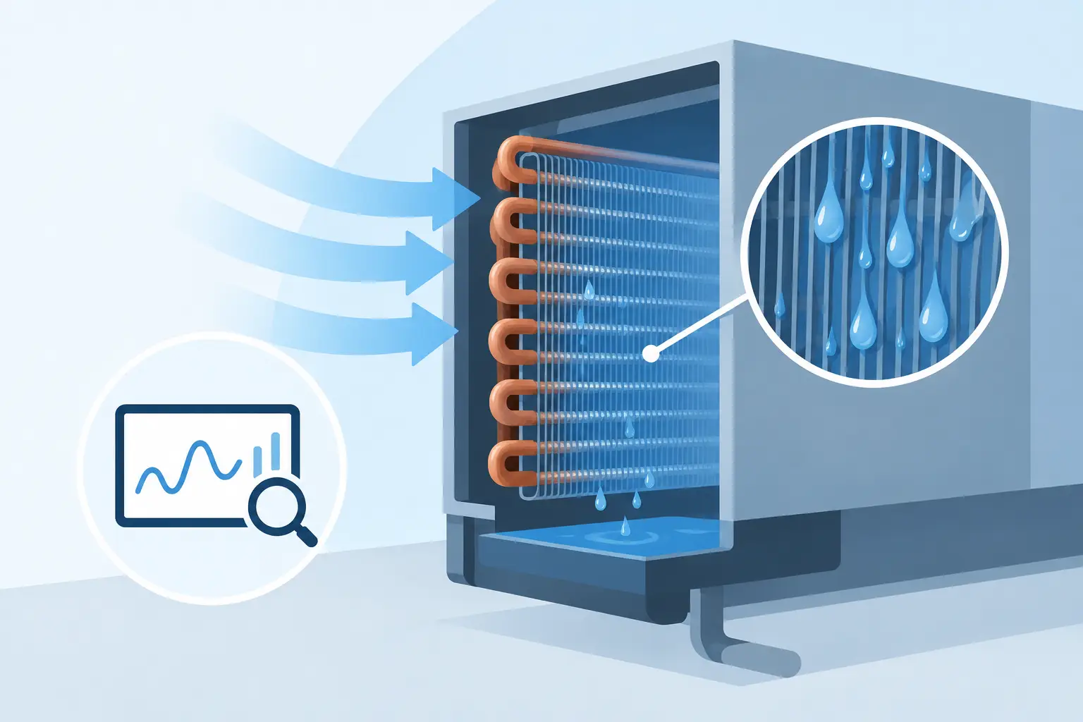
A DX evaporator can meet capacity and leaving-air targets while still creating a downstream moisture problem. To predict coil condensate carryover, the analysis must go beyond total latent capacity and face velocity. Water behavior inside the fin pack, local air acceleration, condensate drainage, and transient operating conditions all determine whether collected condensate remains on the coil or enters the discharge airstream.
For coil designers and HVAC&R engineers, carryover is not a cosmetic concern. It can affect supply-air moisture content, duct cleanliness, fan performance, corrosion risk, and measured unit efficiency. In close-coupled equipment, droplets leaving the coil may also reach downstream components before they can settle.
What Condensate Carryover Actually Represents
Condensate carryover occurs when liquid water formed on the evaporator surface is transported from the coil rather than draining through the fin pack and into the pan. The transport mechanism may be direct droplet entrainment from wet fin surfaces, stripping of liquid films by local air shear, discharge of water from fin bridges, or re-entrainment from a poorly managed drain pan.
This distinction matters because a coil can have adequate nominal drainage but still carry water under a particular combination of airflow and latent load. A steady-state calculation based only on average face velocity may miss the localized conditions that initiate droplet release. Air velocity increases through free-flow passages, changes with frost or debris accumulation, and can be nonuniform across the coil face because of fan, cabinet, and distributor effects.
Carryover risk is therefore a coupled airside, thermal, and drainage problem. The coil does not simply condense a calculated mass of water. It creates liquid on surfaces with specific fin geometry, wettability, flow paths, and exposure to moving air.
Inputs Needed to Predict Coil Condensate Carryover
A credible prediction starts with the coil geometry and the actual operating point. Fin spacing, fin profile, tube arrangement, circuiting, coil depth, and face dimensions influence both airside pressure drop and the pathways available for condensate to migrate. A coil with tighter fin spacing may increase heat transfer area, but it can also reduce drainage clearance and increase the sensitivity to water bridging.
Airside conditions require more than entering dry-bulb temperature and relative humidity. The analysis should establish entering air mass flow, density, face velocity, expected airflow distribution, and leaving-air condition. The condensate generation rate follows from the airside moisture balance, but its effect on carryover depends on where that condensate forms and how quickly it accumulates.
Refrigerant-side conditions also matter. Saturation temperature, superheat distribution, circuit arrangement, and refrigerant mass flow affect surface-temperature distribution across the coil. A coil with a large region operating below the entering-air dew point may produce substantial condensate over its entire depth. Another coil with similar total latent capacity may concentrate condensation in only a few rows, producing different local water loading and drainage behavior.
The operating envelope should include more than the rated condition. Carryover may emerge during high latent load, high airflow, wet-coil pull-down, fan-speed changes, compressor capacity transitions, or reduced drainage capacity. For variable-speed equipment, each relevant airflow and compressor-speed combination should be assessed rather than assuming that a single nominal point represents all modes.
Why Face Velocity Alone Is Not Enough
Face velocity is useful as an initial screening parameter, but it is not the velocity experienced by water within the coil. As air moves through the fin pack, the available flow area is reduced by tubes, fins, louver features, and liquid films. Local velocities through fin passages can be substantially higher than the nominal face value.
Fin geometry also changes the relationship between local velocity and water retention. Louvered fins can improve heat transfer by disrupting boundary layers, yet their geometry may create locations where condensate collects or is exposed to strong local shear. Fin collars, return bends, tube-to-fin contact regions, and areas near the air exit can all become relevant when liquid loading is high.
Drainage is equally influential. Gravity-driven water must move through a complex surface network before reaching the drain pan. Surface coatings, fin alignment, coil tilt, manufacturing tolerances, and contamination can alter that path. A model that calculates condensate production accurately but assumes immediate, unrestricted drainage can understate carryover risk.
A Practical Engineering Workflow
Begin by establishing the coil's thermal state at the intended operating condition. Determine sensible and latent capacity, leaving-air temperature, leaving-air humidity ratio, and total condensate generation rate. This creates the mass-balance foundation, but it should not be treated as the carryover result.
Next, resolve the coil into regions that preserve meaningful changes in air and refrigerant conditions. The objective is to identify where the surface is wet, where condensation is greatest, and where airside velocity and pressure conditions are most likely to disturb retained water. Engineering-grade thermal analysis is particularly valuable here because it can reveal nonuniform surface temperature and load distribution that are hidden by a single average coil condition.
Then evaluate airside flow through the coil geometry. Consider the effective free-flow area, pressure drop, and likely local acceleration through the wet fin pack. If the application has known airflow maldistribution, such as fan proximity or asymmetric cabinet transitions, treat it as a design input. A coil can be acceptable at uniform airflow and problematic when one section receives a disproportionate share of the air volume.
The drainage assessment should examine the direction and continuity of water paths. Ask whether condensate can migrate downward without persistent bridging, whether lower rows are subject to excessive water loading, and whether the pan captures the expected drainage at the selected coil orientation. For horizontal coils, the final rows and lower fin regions often deserve particular attention because they combine accumulated water with high discharge-side air velocity.
Finally, assess the result across an operating map. The critical point may not be maximum capacity. In some designs, carryover is more likely at a moderate refrigeration load combined with elevated indoor airflow, where the coil remains wet but surface tension and drainage do not offset the imposed air shear. Transient conditions should be reviewed separately because water stored on the coil during one state can be released during the next.
Interpreting the Result Without False Precision
Carryover prediction should support engineering decisions, not imply an exact droplet mass fraction when the underlying water-film behavior is uncertain. The most useful output is often a risk assessment tied to physical drivers: low, moderate, or elevated likelihood of entrainment, along with the regions and conditions creating that risk.
A technically useful report identifies the calculated condensate rate, coil wetness distribution, airside velocities, drainage constraints, and sensitivity to airflow. It should also state the assumptions that materially affect the outcome, including fin surface condition, installation angle, airflow uniformity, and drain-pan geometry.
When the predicted margin is small, prototype testing remains appropriate. Visual inspection alone is not always sufficient because fine droplets may not be obvious at the coil exit. Downstream moisture measurement, controlled airflow testing, and repeatable operating conditions provide a better basis for correlating the calculation with physical performance.
Design Changes That Reduce Carryover Risk
The preferred corrective action depends on the source of the problem. Reducing face area loading by increasing coil face area can lower air velocity, but it adds package volume and cost. Increasing fin spacing may improve drainage tolerance, although it can reduce heat transfer surface area or require additional depth. Changes to fin design and surface treatment can improve water shedding, but their long-term performance must be evaluated under contamination and aging.
Airflow management is often as important as coil geometry. Improving inlet distribution, reducing localized bypasses, and avoiding abrupt transitions near the coil can reduce high-velocity regions that strip water from wet surfaces. Where drainage is the limiting factor, coil orientation, pan design, and clearance below the fin pack may provide a more effective solution than changing the thermal design.
ExCoil-style engineering-grade thermal analysis helps place these trade-offs in the right sequence: first establish the thermal and moisture distribution, then evaluate airside and drainage conditions, and finally test only the configurations that show acceptable performance margin.
A coil should be judged not only by how much moisture it removes, but by how predictably it manages that moisture under the conditions the equipment will actually see. That is the basis for carryover decisions that hold up beyond the rating point.