
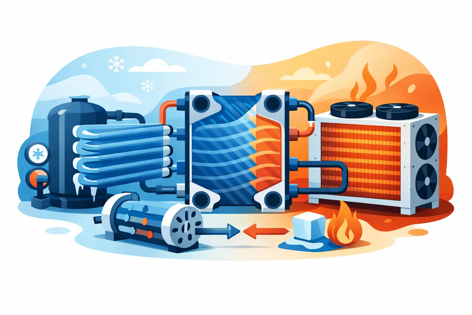
A suction pressure that misses target by a few psi or a condensing temperature that drifts a few degrees can invalidate an otherwise sound coil selection. That is why refrigeration heat exchanger analysis matters at the component level, not just at the system level. For DX evaporators and condensers, small changes in refrigerant-side assumptions, air-side conditions, and geometry can materially shift capacity, pressure drop, superheat behavior, and approach temperature.
For engineers working on product development, coil design, or performance validation, the real question is not whether a heat exchanger transfers heat. The question is how accurately the model represents the coupled behavior of refrigerant phase change, airside heat transfer, pressure losses, and circuiting. Useful analysis has to support design decisions, not just produce a nominal capacity number.
What refrigeration heat exchanger analysis must capture
In refrigeration applications, the heat exchanger is not a static UA problem. A DX evaporator or condenser operates across multiple thermal regions, often with changing refrigerant quality, temperature glide in some cases, and nonuniform local heat transfer coefficients. The analysis must therefore resolve more than bulk inlet and outlet conditions.
For an evaporator, the model typically needs to account for two-phase boiling, superheated vapor region behavior, refrigerant distributor and circuit effects, air temperature and humidity entering the coil, fin efficiency, and both refrigerant-side and air-side pressure drop. If the evaporator is used in a dehumidifying duty, latent load handling is not optional. Surface condition, coil wetness, and airside psychrometrics directly affect total capacity and sensible heat ratio.
For a condenser, the analysis must capture desuperheating, condensation, and subcooling regions. Each region has distinct heat transfer behavior and different sensitivity to mass flux, tube diameter, circuitry, and air face velocity. A condenser that looks acceptable in aggregate may still have an undesirable distribution of area between these regions, leading to weak subcooling or excessive refrigerant pressure drop.
This is where engineering-grade thermal analysis is different from simplified rating tools. A high-level calculator can estimate duty. It cannot reliably predict how a geometry change, circuit count adjustment, or altered refrigerant condition shifts internal thermal balance.
Why coil geometry changes the result
Refrigeration heat exchanger analysis is highly geometry-dependent. Tube diameter, row count, fin spacing, fin type, tube pattern, circuit length, and face area all affect local velocities and transfer coefficients. These are not independent variables, and trade-offs are unavoidable.
Increasing face area can reduce airside pressure drop and improve approach, but it may increase coil footprint beyond packaging limits. Increasing rows may raise total capacity, yet it can also drive airside resistance higher and reduce fan operating margin. Tighter fin spacing may improve dry-surface airside performance, but fouling sensitivity and wet-coil behavior may become less favorable depending on the application.
On the refrigerant side, circuiting is often the most underestimated variable. More circuits can reduce refrigerant velocity and pressure drop, but they may also weaken internal heat transfer if mass flux falls below an effective range. Fewer circuits may improve heat transfer coefficient but create unacceptable pressure losses or unstable distribution. There is no universal best practice. The optimal configuration depends on refrigerant, capacity target, entering conditions, and acceptable operating envelope.
The variables that drive evaporator analysis
DX evaporators are especially sensitive because thermal performance and refrigerant control behavior are linked. The coil does not just absorb load. It determines evaporating temperature, outlet superheat tendencies, and compressor suction conditions.
A rigorous evaporator analysis should evaluate entering air dry-bulb and wet-bulb conditions, refrigerant saturation temperature, superheat target, mass flow rate, distributor assumptions, and finned-surface characteristics. If the application includes medium- or low-temperature refrigeration, frost potential and reduced airside performance over time may also matter, even if frosting is handled outside the base coil model.
One common mistake is to compare evaporator options using total capacity alone. Two coils can produce similar capacity at rating conditions while behaving very differently in practice. One may require higher pressure drop, leading to a lower effective suction pressure. Another may deliver a different sensible-latent split or a different superheat profile. From a system standpoint, those differences are not secondary. They affect compressor lift, control stability, and seasonal performance.
The same caution applies to off-design operation. A coil that performs well at nominal entering air temperature may respond poorly when airflow drops, condensing pressure shifts, or refrigerant feed quality changes. Analysis should test the expected operating range, not a single design point.
Condenser analysis is not just about rejecting heat
Condensers are sometimes treated as simpler because the objective appears straightforward: reject compressor heat and produce adequate subcooling. In practice, condenser sizing and analysis often determine head pressure control, compressor power, and ambient operating limits.
A condenser model should separate the desuperheating, condensing, and subcooling zones and calculate how coil area is distributed among them under each operating condition. That matters because a condenser with insufficient subcooling margin may expose the liquid line and expansion device to instability, especially at elevated ambient or reduced airflow. On the other hand, excessive refrigerant pressure drop through the coil can offset gains in heat transfer performance.
Airside assumptions also deserve scrutiny. Face velocity affects both heat rejection and fan penalty. In many packaged systems, the thermal optimum and the system optimum are not identical. A condenser that improves refrigerant-side performance by driving airflow requirements upward may not be the best design once fan power, sound, and cabinet limits are considered.
Where simplified methods fall short
LMTD and effectiveness-NTU methods remain useful frameworks, but they become limited when applied too loosely to DX refrigeration coils. Phase change, circuit-level nonuniformity, and coupled psychrometric behavior reduce the value of lumped assumptions. If the model treats the entire evaporator or condenser as a single average region, the answer may be directionally correct but still weak for engineering decisions.
The issue is not that simplified methods are wrong. The issue is that they can hide the mechanism behind the result. When performance misses target, the engineer needs to know whether the problem comes from insufficient area, poor refrigerant distribution, excessive pressure loss, weak airside coefficient, or an unfavorable balance between thermal regions. A single top-line capacity result does not provide that insight.
This is why professional HVAC&R software has value beyond speed. It supports repeatable, component-level analysis with enough resolution to test geometry changes, compare circuiting options, and validate design assumptions before prototypes are built.
What to verify in a credible model
When evaluating analysis results, engineers should focus on model inputs and physical consistency before accepting the output. Refrigerant properties must align with the selected fluid and operating range. Airside correlations should be appropriate for the fin geometry and surface condition. Pressure drop calculations should be coupled to thermal performance rather than treated as a cosmetic output.
It is also worth checking whether the model handles dry and wet evaporator operation distinctly, whether phase regions are resolved in condensers, and whether circuit-level effects are represented with enough fidelity for the design stage. The right level of detail depends on the decision being made. Early concept screening does not require the same depth as final design validation. But if the goal is reducing design risk, a model that cannot represent the dominant thermal mechanisms is not enough.
For OEM development teams, another practical test is whether the analysis can support design iteration. If changing tube count, fin density, or circuit arrangement requires manual recalculation outside the tool, engineering throughput suffers and comparison quality drops. Software used for refrigeration heat exchanger analysis should help teams evaluate alternatives systematically, not just document a final answer. ExCoil addresses that need by focusing specifically on engineering-grade thermal analysis for DX evaporators and condensers.
Analysis should serve decisions
The best analysis does not produce the most decimals. It clarifies which variables matter, which trade-offs are acceptable, and where the design margin actually exists. In refrigeration heat exchangers, that usually means understanding how geometry, circuitry, airside conditions, and refrigerant state interact across the full operating envelope.
When the model is detailed enough to explain behavior rather than just report it, engineers can make better decisions earlier - with fewer prototype surprises and less dependence on conservative oversizing. That is where component analysis stops being a calculation exercise and starts becoming an engineering advantage.