
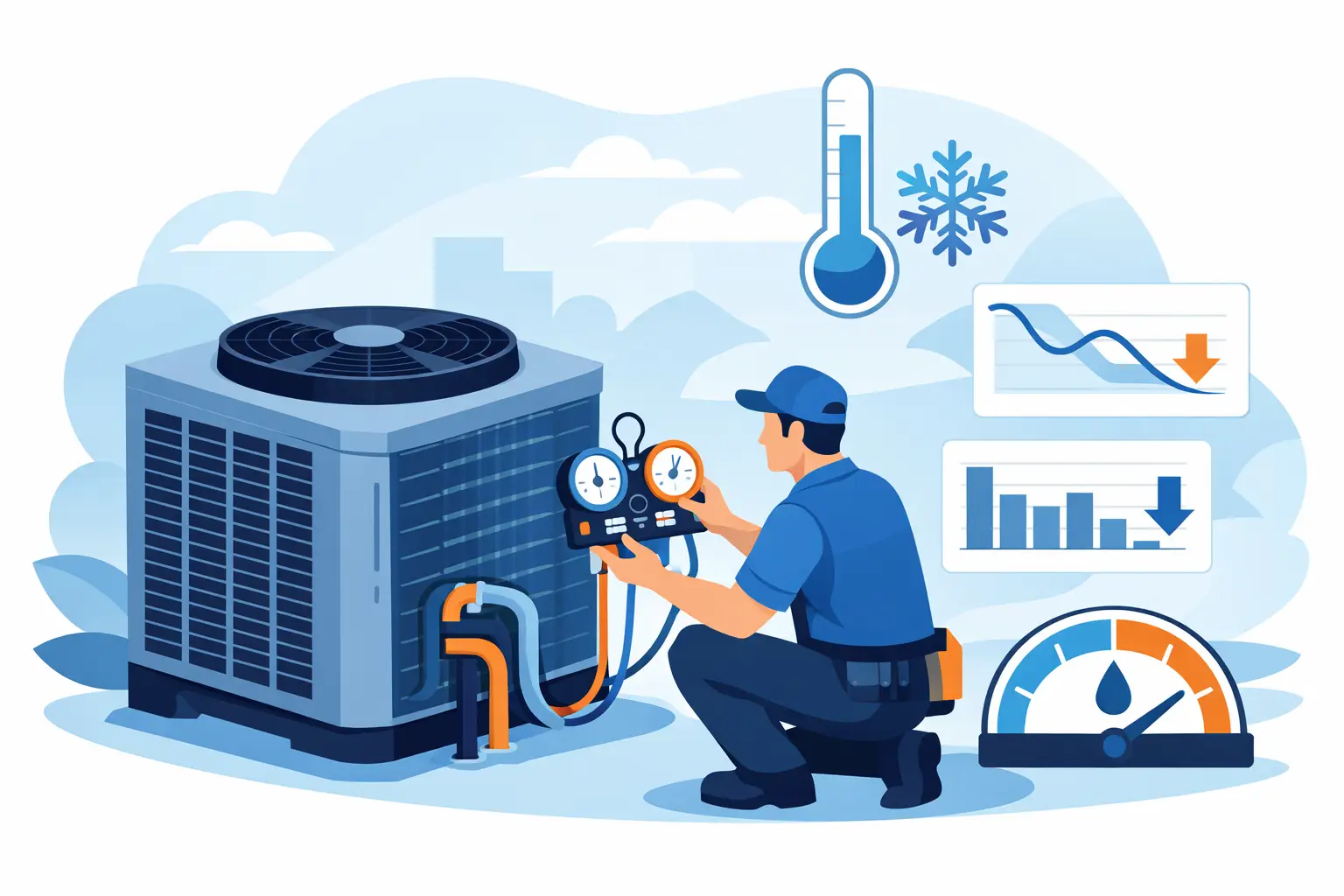
A system that leaves the condenser with marginal liquid quality rarely fails in one dramatic step. More often, it loses capacity, feeds the expansion device inconsistently, and creates operating conditions that look acceptable until ambient shifts or load changes expose the weakness. That is why knowing how to improve condenser subcooling matters. In practice, the answer is not simply adding refrigerant. Subcooling is a coil, circuit, airflow, and system-level result.
What condenser subcooling is really telling you
Condenser subcooling is the temperature difference between the saturated condensing temperature and the actual liquid-line temperature leaving the condenser. In engineering terms, it indicates how much sensible cooling the condensed liquid has received below its saturation point. That margin helps ensure the liquid reaching the expansion device remains fully liquid despite line losses, elevation changes, and ambient exposure.
Higher subcooling is not automatically better. The target depends on the system architecture, refrigerant, receiver arrangement, control strategy, and expected operating envelope. A packaged air-conditioning unit with a short liquid line may tolerate a lower margin than a remote refrigeration system with significant line losses. The objective is not to maximize subcooling blindly. It is to establish enough liquid stability without creating unnecessary condensing pressure, refrigerant inventory, or control side effects.
How to improve condenser subcooling without misdiagnosing the problem
When subcooling is low, the first question is whether the condenser is actually the limiting component. Low measured subcooling can result from undercharge, noncondensables, flash gas in the liquid line, excessive liquid-line pressure drop, insufficient condenser surface, poor airside performance, or unstable head pressure control. These are different failure modes, and they do not respond to the same corrective action.
A useful starting point is to separate measurement from physics. Confirm the pressure used to calculate saturated condensing temperature is taken at a location representative of condenser outlet conditions. Confirm temperature sensors are properly attached and insulated. A few degrees of error can redirect the entire diagnostic process.
After that, evaluate the refrigerant-side heat rejection profile. If the condenser is spending too much of its face area de-superheating vapor and not enough condensing and subcooling liquid, the issue may be compressor discharge superheat, circuit loading, or total condenser capacity. If condensing is complete but the liquid section is too short, the issue is often refrigerant inventory, coil geometry, or control strategy.
Airside improvements that raise subcooling
Condenser subcooling depends on available temperature difference at the liquid end of the coil. If air entering that section is warmer than expected or airflow is nonuniform, the subcooling zone shrinks quickly. Dirty fins, recirculation, fan underperformance, and poor cabinet airflow management can all reduce effective heat transfer.
In air-cooled equipment, verify total airflow and airflow distribution before changing charge. A condenser can show acceptable average airflow and still underperform if one coil segment is starved while another is overloaded. Fan cycling can also create unstable subcooling if active coil area changes too aggressively with ambient. In some cases, a modest increase in face area or a better fan staging sequence produces more reliable liquid formation than raising condensing pressure.
Fin density and tube geometry also matter. A coil selected near its thermal limit may condense adequately at rating conditions but lose subcooling rapidly at elevated ambient or fouled conditions. For OEM design work, this is where engineering-grade thermal analysis becomes useful. It lets you quantify whether the coil has enough condensing and liquid cooling surface at the actual design point instead of relying on nominal catalog assumptions.
Refrigerant-side pressure drop matters more than many designs assume
Internal pressure drop shifts local saturation temperature across the coil. If refrigerant pressure falls significantly between the condensing region and outlet, the apparent subcooling at the outlet can change in ways that complicate interpretation. More importantly, excessive pressure drop consumes part of the available thermodynamic margin.
Circuit design has to balance velocity, oil return, distribution quality, and pressure loss. Very long circuits or circuiting that favors vapor-side performance at the expense of liquid-side stability can limit the net subcooling delivered to the outlet. Header design and distribution into parallel paths also influence whether all circuits contribute evenly to the liquid section.
Refrigerant charge and inventory control
Charge level is often the first lever technicians consider, and for good reason. An undercharged system may not maintain a stable liquid seal in the condenser, reducing or eliminating the dedicated liquid subcooling region. In that case, subcooling will be low because the condenser does not contain enough refrigerant mass to support full condensation and post-condensation cooling.
Still, adding charge is only correct when charge is actually low. If the condenser is airflow-limited or contaminated with noncondensables, adding refrigerant can elevate head pressure without delivering a stable improvement in outlet liquid quality. The result is a system that looks temporarily corrected while consuming more power and operating closer to high-pressure limits.
For systems with receivers, the receiver and condenser function as a combined inventory management system. Seasonal ambient changes, flooded head pressure control, and pump-down sequences can all shift refrigerant distribution. In those systems, target subcooling has to be interpreted in context. A low ambient flooded condenser strategy may deliberately increase inventory in the condenser to preserve head pressure, while a different control arrangement may move more charge into the receiver and reduce measured condenser subcooling.
Head pressure control and ambient operation
Many subcooling complaints are really control problems. In low ambient conditions, insufficient head pressure can reduce expansion valve pressure differential and destabilize flow even if some liquid is present. In response, systems use fan cycling, fan speed control, dampers, or condenser flooding strategies to maintain a usable condensing pressure.
These controls affect subcooling directly. Fan cycling can create step changes in active heat transfer area. Variable-speed fans can improve stability, but the tuning matters. A control loop that chases pressure too aggressively may produce oscillating condensing conditions and inconsistent liquid temperatures. Flooded controls increase subcooling by reducing active condenser area and increasing refrigerant retention, but they also raise refrigerant inventory requirements and can affect startup behavior.
For design engineers, the key point is that condenser subcooling at one steady-state condition is not enough. You need to evaluate how subcooling behaves across the operating map, especially at high ambient, low ambient, and part-load fan states.
Coil design changes that improve condenser subcooling
If the condenser is being designed or re-selected, improving subcooling usually comes down to increasing effective liquid-cooling capacity without creating unacceptable pressure drop or fan power. That can mean more face area, deeper coil geometry, revised row count, different circuiting, or a dedicated subcooling pass.
The best option depends on the application. More rows may increase total heat rejection but also increase airside pressure drop. More parallel circuits may reduce refrigerant pressure drop, but poor distribution can offset the gain. A dedicated subcooling circuit can improve outlet liquid quality, but it adds design complexity and has to be validated against off-design operation.
This is where software-based coil analysis is more reliable than rules of thumb. Subcooling is sensitive to refrigerant distribution, local approach temperature, airside condition, and pressure drop coupling. Small geometry changes can shift the balance between de-superheating, condensing, and subcooling zones in ways that are not obvious from top-level ratings.
Field diagnosis versus design correction
For a field technician or commissioning engineer, the practical sequence is straightforward. Verify the instruments. Confirm condenser airflow and coil cleanliness. Check liquid-line pressure drop and line routing. Evaluate charge against system design intent. Review head pressure control behavior. Only after those checks should the condenser itself be declared undersized or misapplied.
For an OEM or design team, the process is different. The question is not whether today’s unit has low subcooling. It is whether the condenser design produces adequate liquid quality across the expected operating envelope with acceptable fan power, pressure drop, and refrigerant inventory. That requires modeled performance, not just field adjustment.
There is also a trade-off worth stating clearly. Increasing condenser subcooling can improve expansion device stability and protect liquid integrity, but if it is achieved by driving up condensing temperature unnecessarily, compressor power rises. Better subcooling with worse system efficiency is not a clean win. The target is stable liquid delivery at the lowest practical condensing penalty.
How to improve condenser subcooling in a disciplined way
A disciplined answer to how to improve condenser subcooling starts with identifying whether the limiting factor is heat transfer, refrigerant inventory, pressure drop, or controls. From there, corrective action becomes specific: improve airside performance, correct charge, reduce liquid-line or internal pressure losses, stabilize head pressure control, or redesign the coil so the liquid section is adequate at real operating conditions.
For technical teams working on product development or performance validation, that discipline is exactly why detailed condenser modeling matters. Subcooling is not a tuning number in isolation. It is a measurable outcome of the full thermal design. When you treat it that way, the fixes become more accurate, and the system becomes more predictable where it counts - under actual load and ambient variation.
The useful question is not whether you can force more subcooling today. It is whether the condenser can deliver stable liquid tomorrow, at the edge of the envelope, without asking the rest of the system to compensate for a weak design.