
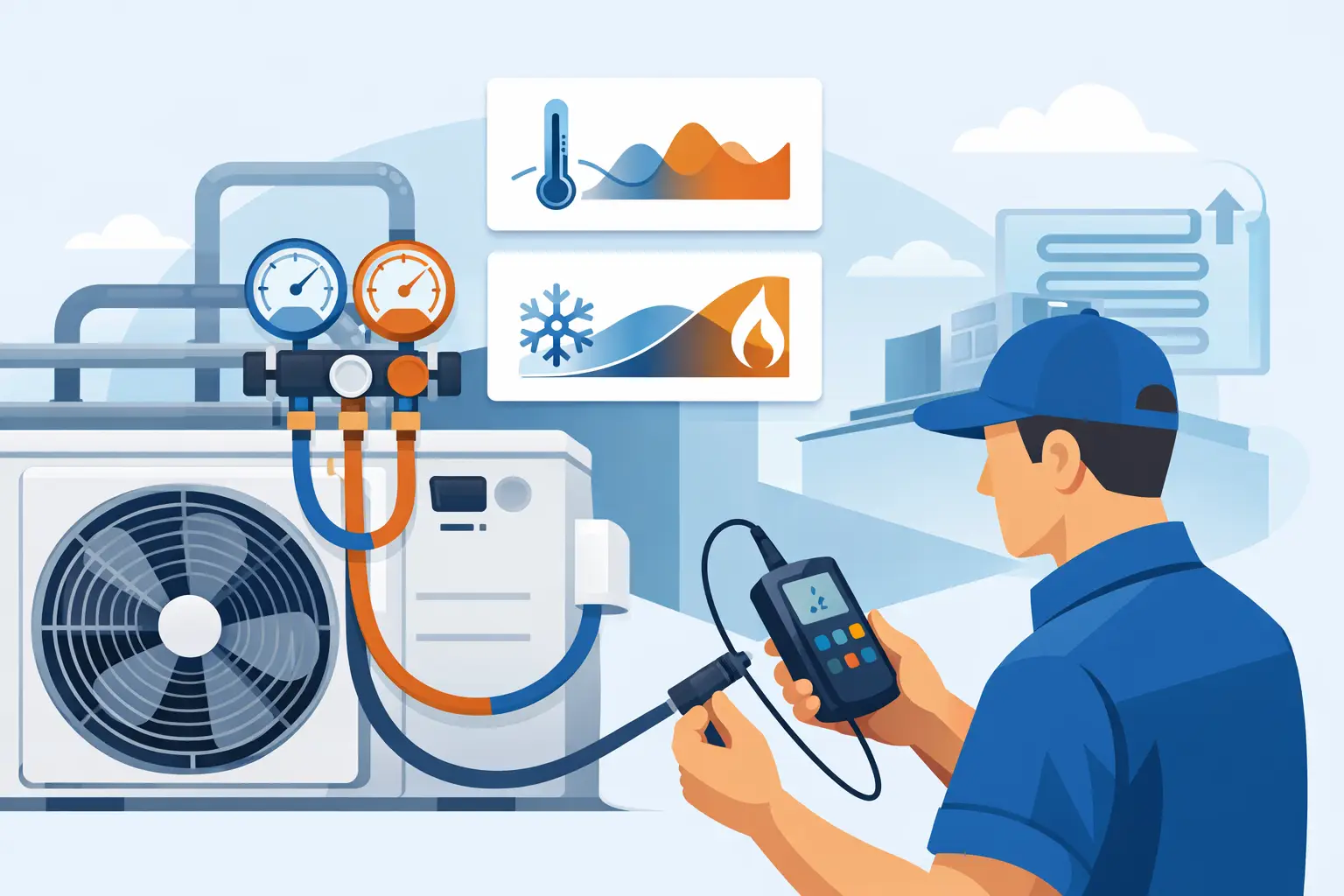
A superheat value is only as useful as the pressure, temperature, and physical location behind it. Knowing how to analyze refrigerant superheat requires more than comparing a suction-line temperature with a pressure-temperature chart. The result must be tied to a defined point in the refrigerant circuit, the applicable saturation condition, refrigerant composition, evaporator load, and control strategy.
For DX evaporators, superheat is both a thermodynamic state variable and a diagnostic indicator. It helps establish whether refrigerant has fully evaporated before entering the compressor, but it does not independently prove that an evaporator is correctly selected, distributed, or loaded. Engineering-grade interpretation begins by separating what was measured from what is inferred.
Define the Superheat Being Evaluated
Superheat is the difference between the actual refrigerant vapor temperature and the saturation temperature corresponding to its local pressure:
Superheat = Actual vapor temperature - Saturation temperature at measured pressure
The definition appears simple, but the phrase “local pressure” is critical. A temperature reading at the evaporator outlet must be paired with the pressure at, or accurately corrected to, that same location. Pairing an outlet temperature with compressor suction pressure introduces the pressure drop across the suction line, fittings, accumulator, and service valves into the calculation. The resulting value may be useful as total system superheat, but it is not evaporator outlet superheat.
In practical analysis, distinguish between evaporator superheat and total superheat. Evaporator superheat is measured near the coil outlet and indicates the vapor condition leaving the evaporator. Total superheat is measured at the compressor inlet and includes heat gain and pressure loss downstream of the evaporator. Both values matter, but they answer different questions.
Establish Accurate Pressure-Temperature Inputs
Pressure must be converted to saturation temperature using the correct refrigerant property relationship. For a pure refrigerant or near-azeotropic blend, this is generally direct. For zeotropic blends with meaningful temperature glide, the appropriate saturation reference depends on the refrigerant state being evaluated.
At the evaporator outlet, refrigerant is vapor or slightly superheated vapor. Use the dew-point saturation temperature for suction-side superheat calculations with zeotropic blends. Using bubble-point temperature at this location can materially overstate calculated superheat. This error becomes more consequential at low evaporating temperatures or with refrigerants that exhibit substantial glide.
Measurement quality matters as much as the property calculation. Pressure transducers should have a range and accuracy appropriate for the expected evaporating pressure. Temperature sensors should be firmly attached to a clean tube surface, insulated from ambient air, and positioned where they represent refrigerant-line temperature rather than local radiant or convective effects. A loosely installed thermocouple on an uninsulated suction line can produce a credible-looking but invalid superheat value.
For steady-state work, allow the system to stabilize before recording data. Compressor cycling, variable-speed operation, demand-based defrost recovery, changing air conditions, and electronic expansion valve hunting can make an instantaneous reading unrepresentative. Logging synchronized pressure, temperature, airflow, and load data is more informative than relying on a single manifold reading.
Analyze Refrigerant Superheat by Location
A disciplined superheat analysis starts with a measurement map. Identify the evaporator inlet, evaporator outlet, sensing bulb or pressure-temperature sensor location, suction-line service port, accumulator inlet and outlet if present, and compressor inlet. Then define the pressure drop between each point.
At the evaporator outlet, measure the refrigerant pressure and tube-wall temperature as close as practical to the outlet connection. Convert that pressure to dew saturation temperature where applicable, then calculate outlet superheat. This value is most relevant when assessing distributor performance, circuit balance, expansion-device control, and the effective utilization of evaporator surface.
At the compressor inlet, repeat the calculation using local suction pressure and temperature. The difference between compressor-inlet superheat and evaporator-outlet superheat reflects downstream heat gain, pressure drop effects, or both. A long suction line routed through a warm mechanical space may add appreciable sensible heat. A restrictive suction line can reduce pressure enough to increase the apparent superheat even when the vapor temperature changes little.
This distinction is especially important when evaluating a system against an expansion valve target. A thermostatic expansion valve bulb typically responds to the temperature and pressure relationship near its sensing location. If the bulb is installed at the evaporator outlet, its controlled superheat should be compared with outlet conditions, not with a compressor service-port reading several feet away.
Interpret High and Low Values in System Context
High superheat generally indicates that a substantial portion of the evaporator is operating with dry vapor rather than boiling refrigerant. It may result from insufficient refrigerant feed, but that is not the only explanation. Low entering-air temperature, reduced airflow, low load, a restricted liquid line, inadequate subcooling at the expansion device, a plugged distributor port, or incorrect valve adjustment can all contribute.
Low superheat suggests that the boiling process extends close to the evaporator outlet. In a controlled DX system, a low but stable value may be appropriate under design load. Extremely low or unstable superheat, however, increases the risk of liquid carryover and can indicate an overfeeding expansion device, a misplaced sensor bulb, poor pressure equalization, or transient load changes beyond the control response of the valve.
Neither condition should be diagnosed from superheat alone. Consider evaporating temperature, condenser conditions, liquid subcooling, airflow or water flow, refrigerant charge, compressor capacity, and expansion-device behavior. A low-load comfort-cooling coil and a medium-temperature refrigeration evaporator should not be expected to operate at the same superheat target. The appropriate range depends on coil geometry, circuiting, refrigerant, control architecture, and the acceptable balance between coil utilization and compressor protection.
Separate Expansion-Device Behavior From Coil Performance
Superheat is often treated as a direct measure of refrigerant charge. That shortcut is unreliable, particularly on systems using TXVs or electronic expansion valves. These devices regulate refrigerant feed in response to a controlled condition, so charge-related problems may first appear as loss of liquid subcooling, flash gas at the valve inlet, unstable control, or capacity degradation rather than a predictable superheat shift.
For fixed-orifice systems, superheat can be more sensitive to charge and operating conditions, but the same caution applies. Ambient condition, indoor load, airflow, and compressor performance all influence the result. A charge decision should therefore use manufacturer procedures and a complete set of operating measurements.
At the coil level, nonuniform refrigerant distribution can create a misleading average. One circuit may leave with very high superheat while another remains wet, especially in multi-circuit evaporators operating at part load. A single outlet measurement cannot reveal the internal distribution pattern. Coil design review should consider circuit arrangement, distributor selection, feeder pressure drop, tube circuitry, air-side velocity profile, and the thermal load assigned to each circuit.
Professional HVAC&R software can support this work by modeling local refrigerant states, pressure losses, air-side conditions, and circuit-level heat transfer. ExCoil-style thermal analysis is most valuable when measured superheat is used as one validation point within a complete evaporator performance model, rather than as a stand-alone pass/fail metric.
Use a Repeatable Analysis Sequence
A reliable workflow begins by documenting the refrigerant, operating mode, control type, sensor locations, and current load conditions. Record suction pressure and line temperature at the same defined point. Determine the correct saturation temperature, using dew point for applicable zeotropic blends, and calculate superheat.
Next, calculate superheat at any additional locations needed to separate evaporator behavior from suction-line effects. Compare those values with the expansion-device sensing location and the intended control target. Review pressure drop from the coil outlet to the compressor, then assess liquid-line subcooling, entering and leaving air or water temperatures, airflow, and capacity indicators.
If the result is abnormal, avoid changing charge or valve adjustment immediately. First verify sensor placement and instrument accuracy. Then confirm that airflow, load, and condensing conditions are within the expected operating envelope. Only after those conditions are established should the analysis move toward refrigerant feed, charge, restriction, or control faults.
A useful superheat calculation does not merely produce a number. It establishes where vaporization ends, how the expansion device is responding, and whether the evaporator is using its available heat-transfer surface as intended. When the measurement boundary is explicit and the coil is evaluated as a coupled thermal system, superheat becomes a defensible engineering input rather than a convenient field assumption.