
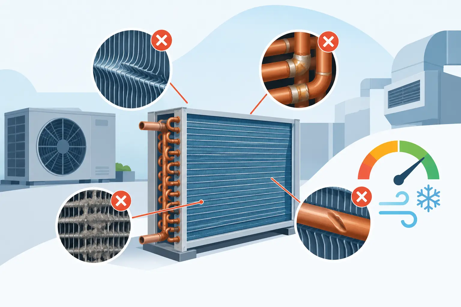
A coil can meet its nominal capacity target on a worksheet and still fail the product requirement once it is installed in a cabinet, connected to real piping, and exposed to a realistic air stream. The most costly coil design errors are rarely obvious dimensional mistakes. They are modeling and assumption errors that distort the relationship among airside resistance, refrigerant distribution, heat transfer, pressure drop, and operating controls.
For DX evaporators and condensers, a valid design is not simply the highest-capacity geometry at one rating point. It must produce acceptable performance across the operating envelope while remaining manufacturable, drainable, serviceable, and compatible with the system's compressor and expansion device.
Where Coil Design Errors Begin
Many design reviews begin with tube rows, fin density, face area, and circuit count. Those inputs matter, but they do not independently define coil performance. A change to one variable shifts several others. Adding fin density may increase heat transfer area, for example, while raising airside pressure drop, fan power, fouling sensitivity, and the risk that actual airflow falls below the rating assumption.
The error is treating these interactions as secondary checks. In an engineering workflow, they are part of the primary design problem.
Using a single-point rating as the design basis
A coil selected at one outdoor ambient, entering-air temperature, airflow, and condensing or evaporating temperature can appear well balanced. Equipment does not operate at one point. An air-conditioning evaporator may encounter reduced airflow, elevated latent load, varying return-air conditions, and expansion-valve response that changes refrigerant distribution. A refrigeration evaporator may operate through pull-down, frost accumulation, defrost recovery, and low-load cycling.
Condensers face a different but equally significant range. Ambient temperature, airflow recirculation, fan staging, subcooling requirement, and compressor operating conditions change the required heat rejection and allowable refrigerant-side pressure loss.
A design should therefore be evaluated at the conditions that govern product risk, not only at the published rating condition. This includes off-design capacity, sensible heat ratio where applicable, refrigerant outlet condition, airside pressure drop, refrigerant pressure drop, and approach temperature. The governing point may be a hot ambient condition, a low-evaporating-temperature case, or a part-load condition rather than the nominal rating.
Treating airflow as uniform
Thermal models often begin with a uniform face velocity. Installed coils seldom see one. Fan location, shrouding, cabinet clearances, filters, electric heaters, drain pans, and downstream restrictions can create regions of low velocity or bypass flow. A coil may have sufficient modeled face area yet exhibit poor air distribution in the assembly.
This matters because local air velocity affects both the airside heat transfer coefficient and local refrigerant loading. On an evaporator, low-flow regions can promote low superheat or frosting while high-flow regions remain underutilized. On a condenser, nonuniform airflow can reduce effective heat rejection and raise condensing pressure beyond expectations.
The practical response is not to assume that every coil requires full computational fluid dynamics. It is to use realistic airflow inputs and identify when cabinet geometry or fan selection makes a uniform-flow assumption unacceptable. Airside pressure drop should also be calculated at actual operating airflow, including the effects of wet surfaces and frost where relevant.
Refrigerant Circuiting Errors Have System-Level Consequences
Circuiting determines more than refrigerant velocity. It controls pressure drop, distribution quality, oil return behavior, local heat flux, and the degree to which each portion of the coil can contribute at off-design conditions.
Over-circuiting or under-circuiting the coil
Too many parallel circuits can reduce refrigerant velocity to a point where distribution becomes difficult and oil return margins narrow. Too few circuits can create excessive refrigerant-side pressure drop, reducing effective evaporating pressure or increasing condensing pressure. Either condition can lower system efficiency even if the coil's calculated duty appears adequate.
The correct circuit count depends on refrigerant, mass flow rate, tube diameter, circuit length, orientation, pressure-drop allowance, and distributor capability. It also depends on the application. A comfort-cooling evaporator and a low-temperature freezer evaporator may require different velocity and distribution priorities despite having similar nominal capacities.
Circuit symmetry deserves particular attention. Equal tube count does not guarantee equal circuit resistance. Header geometry, feeder tube lengths, elevation changes, return bends, and local two-phase behavior can produce unequal mass flow among nominally identical paths. Unequal distribution is especially damaging in evaporators because starving one region and overfeeding another can coexist within the same coil.
Ignoring pressure drop as a thermal variable
Refrigerant pressure drop is often reported as a separate hydraulic result. For two-phase DX applications, that separation can hide the real consequence. A pressure reduction changes saturation temperature and therefore changes the local temperature difference available for heat transfer. The coil does not experience one fixed evaporating or condensing temperature from inlet to outlet.
This is why simplified calculations can overstate capacity or misrepresent the required surface area. The impact becomes more pronounced with long circuits, high mass flux, low-temperature operation, high-pressure refrigerants, and designs with aggressive circuit loading. Engineering-grade thermal analysis should couple refrigerant pressure drop with the local heat-transfer calculation rather than applying a single average temperature difference.
Airside Geometry Can Solve One Problem and Create Another
Fin spacing, fin pattern, tube arrangement, row depth, and face velocity should be selected as an integrated airside design. Pursuing compactness without considering the operating environment is a common source of field underperformance.
A dense-fin evaporator may provide attractive dry-coil capacity. In a high-latent application, condensate bridging, retained water, and particulate loading can quickly change its pressure-drop curve. In low-temperature refrigeration, frost growth may dominate the usable operating interval. Wider fin spacing can reduce initial surface area, yet deliver better capacity retention between defrost cycles and reduce fan-energy penalties.
Condenser geometry carries similar trade-offs. Tighter fins can improve clean-coil heat transfer but may be unsuitable where cottonwood, dust, grease, or industrial contaminants are expected. A design that requires unusually frequent cleaning to maintain rated performance transfers risk from the laboratory to the owner.
Tube geometry also requires restraint. Smaller tubes can reduce internal volume and support certain compact designs, but they change pressure-drop behavior, circuiting options, manufacturing tolerances, and service considerations. There is no universally optimal tube diameter or fin density. The selection must follow the duty, refrigerant, airflow source, fouling environment, and allowable fan power.
Condensate, Frost, and Defrost Are Not Secondary Details
An evaporator that cannot remove water predictably is not a finished design. Coil orientation, fin collars, tube pattern, casing clearance, drain-pan geometry, and air velocity all influence water carryover and drainage. In a comfort-cooling application, retained water can affect airside pressure drop, microbial control, and latent performance. In refrigeration, freeze-up can obstruct airflow and shorten the time between defrosts.
Defrost assumptions must be tested against the actual coil mass, circuiting, fin spacing, and installation configuration. A coil may defrost adequately in a simplified thermal model yet retain ice in shielded areas, at return bends, or near the drain pan. Electric, hot-gas, and off-cycle defrost strategies impose different constraints. The coil geometry should support the chosen method rather than forcing controls to compensate for unfavorable geometry.
Validate Coil Designs as Operating Systems
The strongest protection against coil design errors is a validation process that connects geometry to operating behavior. Start with verified boundary conditions: entering-air state, airflow range, refrigerant type, mass flow, saturation conditions, superheat or subcooling target, and acceptable pressure drops. Then evaluate the coil across a defined matrix of credible conditions.
For each condition, review capacity alongside the variables that explain whether the result is usable: airside pressure drop, refrigerant pressure drop, outlet superheat or subcooling, circuit-to-circuit loading, face velocity, fan power, and frost or condensate implications. If a change improves one metric, identify what it degrades. That discipline prevents a nominal capacity improvement from becoming a system penalty.
Manufacturing constraints should enter the analysis early. Distributor selection, brazed-joint access, tube expansion quality, fin tooling, header design, allowable circuit complexity, and test repeatability all influence whether calculated performance can be reproduced in production. A design with marginal performance sensitivity may be unsuitable if normal build variation moves it outside the allowable range.
Professional HVAC&R software is valuable when it makes these relationships visible rather than reducing the coil to a single capacity result. ExCoil supports this type of engineering-grade thermal analysis for DX evaporators and condensers, where local thermal behavior and refrigerant-side effects must be evaluated together.
A well-designed coil is not the one that looks best at a single rating point. It is the one whose performance remains explainable, controllable, and repeatable when airflow shifts, refrigerant conditions move, surfaces become wet or frosted, and the equipment enters the operating conditions it will actually see.