
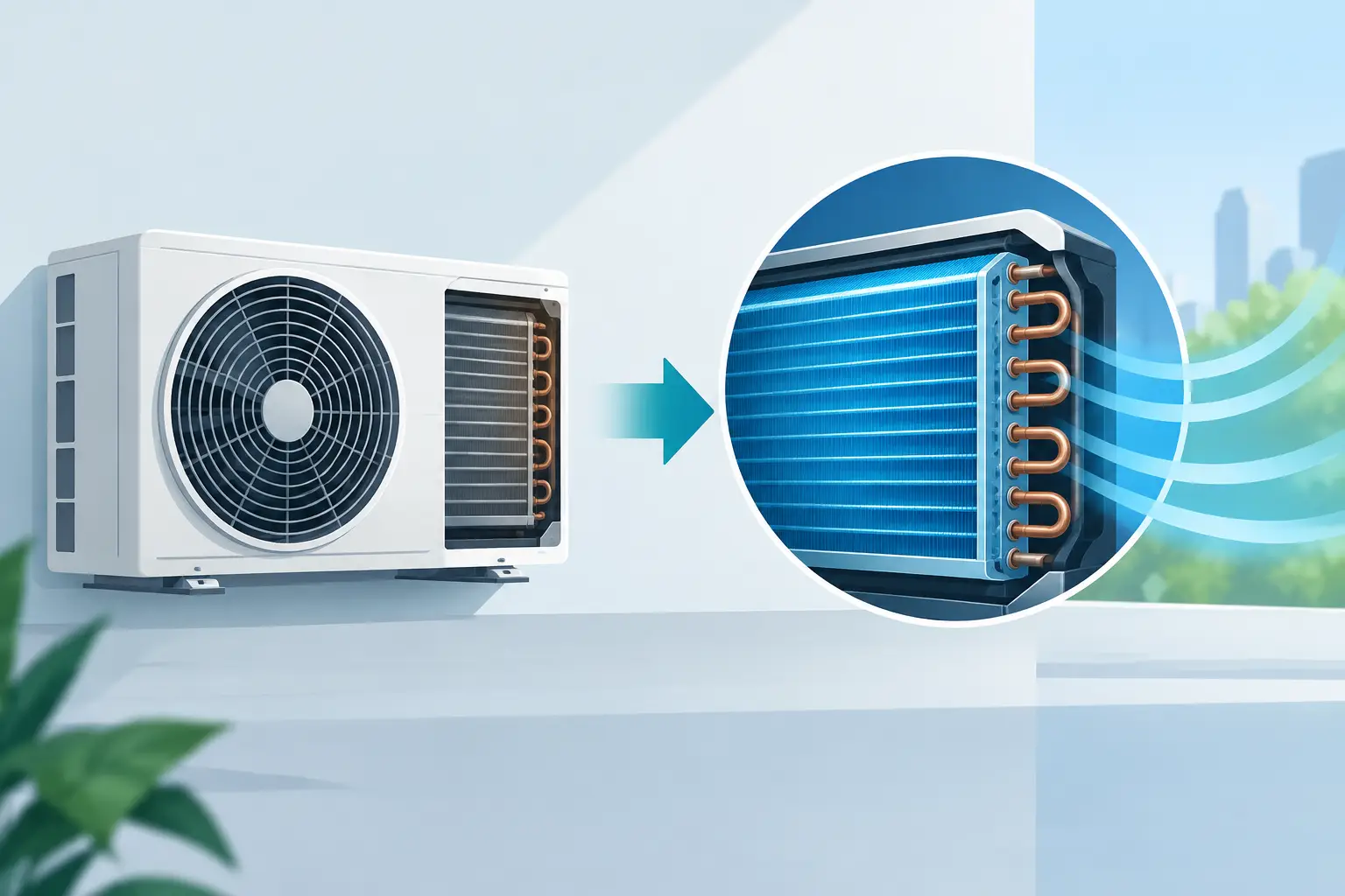
A 10% capacity shortfall at the rating point is rarely caused by one isolated variable. In an air conditioner redesign, a revised fin pattern, circuit count, tube diameter, fan selection, or refrigerant charge strategy can shift the entire balance between heat transfer, pressure drop, latent capacity, compressor operating conditions, and manufacturability. The engineering task is not to make one component look better in isolation. It is to establish whether the revised unit delivers its required performance across the operating envelope.
Air Conditioner Redesign Starts With a Defined Baseline
Redesign decisions should begin with a validated baseline model and measured reference data where available. A nominal capacity value alone is insufficient. Engineers need the original coil geometry, circuiting arrangement, tube and fin details, airside conditions, refrigerant type, compressor map assumptions, fan curve, charge condition, and control logic. Without that definition, a comparison between the existing and proposed design can confuse model assumptions with actual design improvement.
The baseline must also be tied to the duty that matters. For a comfort-cooling split system, that may include rated cooling, high-ambient operation, part-load conditions, and dehumidification performance. For a packaged or refrigeration application, the governing conditions may include elevated condensing temperatures, low-load stability, pull-down behavior, or constrained evaporating temperatures. The most useful redesign target is therefore a performance map, not a single-point result.
Measured data should be reviewed for uncertainty before it is used for calibration. Airflow measurements, entering-air psychrometrics, refrigerant mass flow, superheat, subcooling, and pressure sensor placement all influence the apparent coil result. A model calibrated to inconsistent test data can produce a precise-looking but misleading redesign recommendation.
Define the Real Constraint Before Changing Coil Geometry
Many redesign programs begin with an assumed solution: add rows, increase face area, use a denser fin, or divide the refrigerant flow into more circuits. Each can be valid, but each moves a different set of constraints.
Increasing coil surface area can raise capacity, but it may increase material cost, cabinet size, refrigerant volume, or airside pressure drop. A denser fin pattern can improve airside heat transfer under some conditions, yet it also raises fan power and can degrade performance as dust accumulation or condensate retention increases. Additional refrigerant circuits can reduce refrigerant-side pressure drop, but poor circuit loading or maldistribution may offset the expected gain.
The governing constraint is often more specific than capacity. An OEM may need to meet a seasonal efficiency target with an existing blower. A compact product may have a fixed coil envelope. A refrigerant transition may impose new pressure-drop and charge-management limitations. A redesign intended to improve latent performance may be limited by coil surface temperature, airflow distribution, and expansion-device control rather than total coil UA.
Engineering-grade thermal analysis is useful because it separates these effects. It evaluates local heat transfer and pressure-drop behavior along the circuit rather than treating the heat exchanger as a single black-box capacity value.
The Evaporator Is a Coupled Airside and Refrigerant-Side Problem
For DX evaporators, coil performance depends on how the refrigerant evaporates through the circuit and how air is distributed over the face. The refrigerant does not enter the coil at a uniform quality and leave with a uniform thermal history. It passes through two-phase regions, may approach dryout, and commonly completes its path in a superheated region. The location and extent of those regions affect both capacity and leaving-air conditions.
Circuit design determines refrigerant mass flux, pressure drop, and the progression of saturation temperature through the coil. A circuit that is too long may have excessive pressure drop and reduced effective evaporating temperature. A circuit that is too short may operate at a low mass flux or create distribution sensitivity. Parallel circuits need reasonably equal refrigerant feeding, particularly when distributor design, feeder lengths, coil orientation, or operating transients create unequal flow resistance.
Airside nonuniformity is equally significant. A face-velocity average can hide bypass zones caused by fan discharge patterns, cabinet obstructions, return-air geometry, or uneven fin loading. If the coldest and most active refrigerant region aligns with a low-airflow area, modeled capacity may not translate to tested capacity. For latent applications, uneven airflow also changes local surface temperatures and condensate formation, affecting sensible heat ratio and drainage behavior.
A credible redesign model should therefore represent the actual coil circuitry and use realistic air distribution assumptions. When detailed velocity data is unavailable, engineers should at least evaluate sensitivity to plausible maldistribution rather than relying only on perfectly uniform airflow.
Condenser Changes Must Be Evaluated at the System Level
Condenser redesign is often pursued to reduce condensing temperature, recover capacity at high ambient, or improve efficiency. The apparent path is straightforward: increase heat rejection. In practice, the condenser influences compressor lift, refrigerant charge distribution, subcooling, expansion-device inlet condition, and fan energy.
More condenser surface can lower the refrigerant-to-air temperature difference needed to reject heat. However, an increase in rows or fin density can also increase external static pressure. If the existing fan is retained, airflow may fall enough to dilute the expected thermal benefit. If a larger fan is selected, the energy and acoustics penalty must be included in the system comparison.
Refrigerant-side pressure drop also requires attention. At high ambient conditions, pressure loss through the condenser reduces the pressure available at the expansion device and may alter liquid inventory. The redesigned coil must maintain stable liquid delivery under the relevant range of ambient conditions, airflow levels, and charge states. A condenser that shows a favorable heat-rejection result at one charge condition can still create control or subcooling problems at another.
Use a Disciplined Air Conditioner Redesign Workflow
A practical workflow moves from performance definition to component-level analysis, then back to system verification. First, specify the required operating points, tolerances, physical envelope, allowable fan power, refrigerant charge limits, and manufacturing constraints. Next, create or validate a detailed model of the existing evaporator or condenser, including geometry, refrigerant circuitry, and airside resistance.
The proposed changes should be evaluated as controlled cases. Change one primary design variable or a tightly defined group of variables, then compare capacity, sensible and latent split where relevant, refrigerant pressure drop, airside pressure drop, required airflow, refrigerant inventory, and approach temperatures. This makes trade-offs visible and prevents a favorable result from being attributed to the wrong mechanism.
Sensitivity analysis is especially valuable when inputs are uncertain. Airflow, fin efficiency, contact resistance, refrigerant distribution, and compressor mass flow can all vary from nominal assumptions. A design with slightly lower modeled peak capacity may be preferable if it remains within target across reasonable variations in airflow and charge. That distinction matters in production equipment, where tolerance stack-up and field installation conditions are unavoidable.
Professional HVAC&R software such as ExCoil can support this process by providing detailed thermal analysis for DX evaporators and condensers. The objective is not merely a faster calculation. It is a defensible connection between coil geometry, circuit behavior, thermal performance, and the system-level consequences of a design change.
Validate What the Model Cannot Fully Capture
Thermal modeling should guide redesign, not replace hardware validation. Prototype testing remains necessary for airflow distribution, refrigerant maldistribution, condensate carryover, frost behavior where applicable, acoustic effects, control interactions, and fabrication details that are difficult to represent fully in a component model.
Test plans should be designed to answer the questions raised by the analysis. If a redesign depends on reduced airside pressure drop, measure coil pressure drop and system airflow at the operating speed. If it depends on improved refrigerant distribution, instrument branch temperatures and pressures where practical. If a latent-capacity improvement is expected, measure leaving-air dry-bulb and humidity with sufficient accuracy to separate sensible and latent effects.
When model and test results disagree, the gap is useful engineering evidence. It may reveal an incorrect boundary condition, unmodeled air bypass, circuiting behavior, or a measurement issue. Treating that gap as a calibration opportunity produces a stronger design method for the next iteration.
The best redesign is not necessarily the coil with the highest simulated capacity. It is the design that meets required performance with controlled pressure drops, stable refrigerant behavior, acceptable fan energy, manufacturable geometry, and enough margin to perform outside the laboratory.