
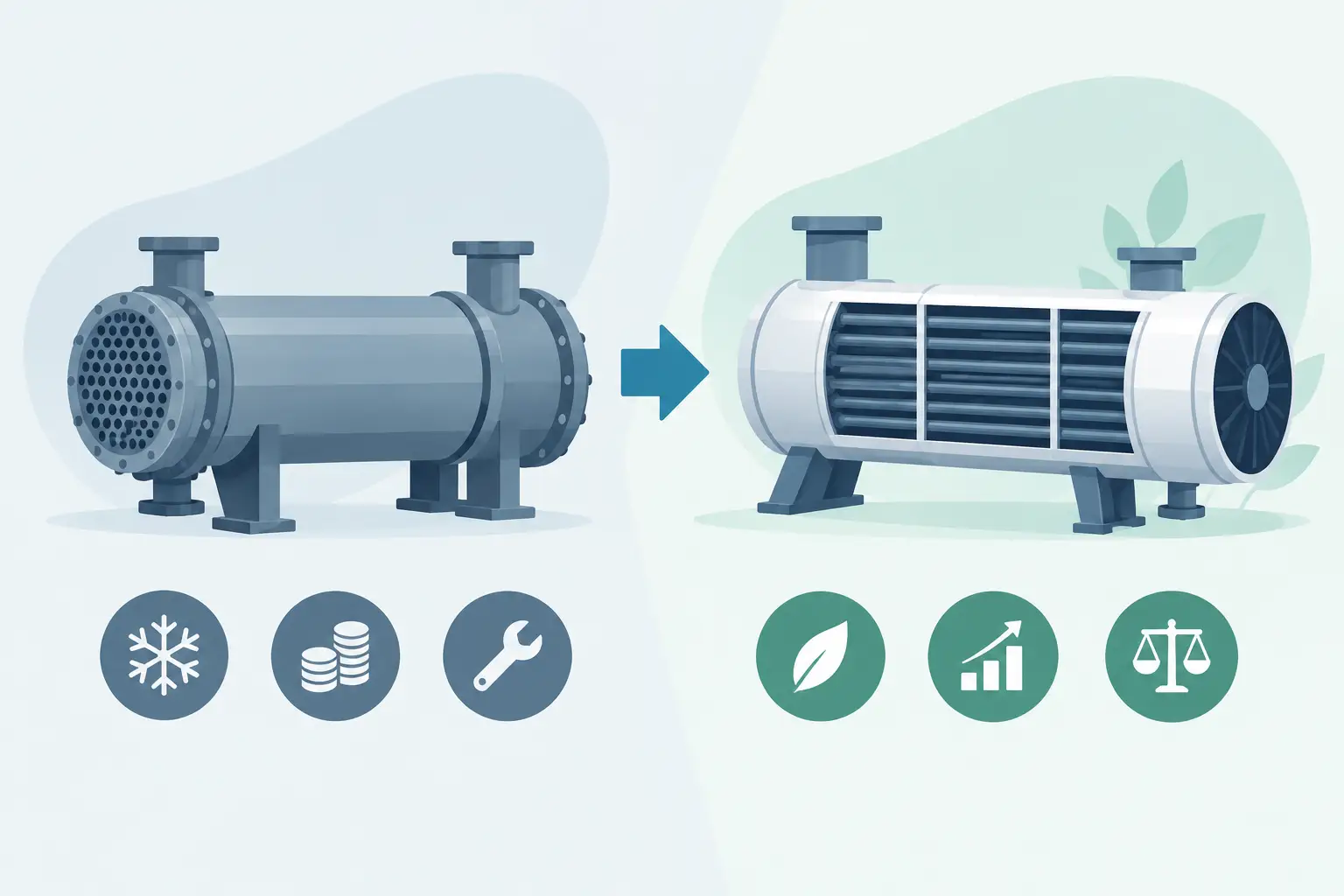
A condenser that misses its capacity target at a 95°F ambient condition is rarely corrected by simply adding more surface area. The result may be lower condensing temperature, but it can also be higher air-side pressure drop, more fan power, greater refrigerant charge, uneven circuit loading, or a coil that is difficult to manufacture. This condenser redesign example examines how an engineering team can evaluate those interactions before committing to a prototype.
The case is representative of an air-cooled DX condensing unit used in commercial refrigeration or packaged HVAC equipment. The purpose is not to prescribe a universal geometry. It is to show the calculation sequence required to turn a performance complaint into a defensible coil redesign.
Starting Point: The Design Constraint
Assume an OEM has an existing condenser rated at 100,000 Btu/h with R-454B under a specified full-load condition. During validation, the unit delivers only 93,000 Btu/h at 95°F entering-air temperature. The measured condensing pressure is above the intended control range, compressor power rises, and system efficiency falls.
The original coil has 3/8-inch copper tubes, aluminum fins, 10 fins per inch, a two-row depth, and a face area constrained by the condensing section enclosure. Airflow is supplied by an axial fan with limited available static pressure. The redesign must recover the capacity deficit without changing cabinet width, increasing sound beyond the product requirement, or creating an unacceptable refrigerant-side pressure drop.
This is the point where simplified rules such as add a row or increase fin density become risky. Condenser performance is governed by the coupled behavior of refrigerant desuperheating, condensation, and liquid subcooling; air-side heat transfer and pressure drop; tube-side pressure loss; and the distribution of refrigerant across circuits. A geometry change affects several of these variables at once.
Condenser Redesign Example: Establish the Baseline Model
The first task is to establish a credible baseline. A thermal model should reproduce the original coil geometry, tube pattern, fin type, circuit arrangement, fan curve, refrigerant condition, entering-air condition, and any known allowance for airflow bypass or recirculation.
For this case, the engineering team models the refrigerant entering the condenser at the compressor discharge mass flow and enthalpy associated with the full-load operating point. The coil is divided into sufficiently small elements so that local air temperature, refrigerant quality, heat transfer coefficient, and pressure loss can change across the coil. Treating the entire condenser as a single average-temperature section can obscure the limits created by phase change and circuiting.
The baseline analysis confirms a predicted capacity of approximately 94,000 Btu/h, which is close enough to the test result to support design comparisons. It also reveals an uneven thermal distribution. The first portion of the circuit is dominated by desuperheating, while the downstream portion has limited effective area for condensation and subcooling. Air leaving the coil is warmer near one region of the face, indicating that the current circuit arrangement is not using the available air stream evenly.
Before changing the coil, the team should verify whether the deficiency is truly a coil problem. A fouled fin surface, fan rotation error, inadequate shroud clearance, hot discharge-air recirculation, or actual airflow below the assumed value can produce similar symptoms. A redesign cannot compensate reliably for an installation or airflow-system error.
Selecting Variables That Address the Actual Limit
With the baseline validated, the team evaluates design variables individually and in combinations. In this example, face area cannot increase, so the principal options are a third tube row, higher fin density, revised circuitry, and a change in tube diameter or internal enhancement.
Adding a third row increases external surface area and can improve heat rejection, but it also raises air-side resistance. If the existing axial fan operates near the steep portion of its curve, the added coil depth may reduce airflow enough to offset part of the expected gain. The proper calculation couples the coil air-side pressure drop with the fan curve rather than holding airflow constant.
Increasing fin density from 10 to 12 fins per inch creates more external area, yet the benefit depends on fin efficiency, tube spacing, face velocity, and contaminant tolerance. Closely spaced fins may be acceptable in a clean indoor application but can reduce field performance where cottonwood, grease, or dust loading is expected. The coil must meet its rating condition and remain serviceable through the intended maintenance interval.
Circuiting is often the highest-leverage change. Splitting the refrigerant into more parallel paths can lower refrigerant pressure drop and reduce the temperature glide associated with pressure loss. However, too many circuits may reduce refrigerant mass velocity, weaken internal heat transfer, and make distribution more sensitive to header design. Circuit count cannot be selected from tube length alone.
For the modeled unit, the most effective configuration is not the maximum possible surface area. The selected candidate uses three rows, retains 10 fins per inch, and changes the refrigerant arrangement from two long circuits to four shorter, balanced circuits. A modest increase in face velocity is accepted, while the fan and shroud are adjusted to maintain airflow within the acoustic limit.
Evaluate Capacity, Pressure Drop, and Fan Power Together
The revised model predicts 104,500 Btu/h at the original rating condition. That margin is intentional. Production variation in fin forming, tube expansion, airflow, fan performance, and refrigerant charge can consume a nominal 7 percent gain quickly. The target should be a design margin supported by tolerance analysis, not an arbitrary oversizing factor.
The thermal result alone is insufficient. The revised coil produces a higher air-side pressure drop, and the fan operating point shifts from 7,800 cfm to 7,450 cfm. Fan input rises by 38 W after the fan change. This penalty is acceptable only because the lower condensing temperature reduces compressor power by more than the added fan power at the design condition.
On the refrigerant side, the shorter circuits reduce coil pressure drop despite the additional row. That result improves the effective saturation temperature available for heat rejection. The model also shows a more even distribution of condensation across the coil face, which reduces the likelihood that one circuit exits with insufficient subcooling while another carries excess liquid inventory.
The redesign must be checked at more than one operating point. At lower ambient temperature, increased condenser effectiveness may drive excessive subcooling or alter receiver inventory behavior. At high ambient, the fan curve and compressor envelope become more consequential. Part-load conditions may expose control instability if head-pressure control was tuned around the original coil. A professional HVAC&R analysis therefore evaluates a condition matrix, not a single rating point.
Design Details That Can Invalidate a Good Model
A coil model represents the geometry and boundary conditions supplied to it. If the physical design cannot reproduce those inputs, the apparent optimization has little value. Header design deserves particular attention when a redesign increases circuit count. Equal nominal circuit length does not ensure equal refrigerant distribution. Header pressure gradients, outlet orientation, branch placement, and phase separation at the inlet can produce circuit-to-circuit maldistribution.
Manufacturing constraints also matter. A third row can affect tube expansion quality, brazing access, fixture design, coil weight, and shipping durability. Fin collars and tube spacing must remain compatible with the production line. The engineering release should identify dimensions that are performance-critical rather than assuming normal fabrication variation is harmless.
For refrigerants with temperature glide, the analysis should use the appropriate local thermophysical properties and distinguish between dew-point and bubble-point temperatures where relevant. For all refrigerants, pressure drop must be translated into its effect on local saturation temperature rather than reported as an isolated number. This is especially relevant near the outlet, where liquid fraction, mass flux, and subcooling behavior change rapidly.
Use Testing to Close the Loop
The prototype test plan should measure more than capacity. Record entering and leaving air temperatures, airflow or fan operating data, refrigerant pressures, line temperatures, compressor power, fan power, and refrigerant-side temperature changes at practical circuit locations. Infrared imaging can help identify large face-temperature nonuniformities, although it should not replace calibrated thermal measurements.
If measured capacity differs from the model, reconcile the inputs before altering the geometry again. Differences frequently originate in actual airflow, bypass paths, fan heat, refrigerant charge, or test-condition stabilization. Updating the model with verified prototype data turns the first redesign into a more reliable engineering asset for future platforms.
ExCoil-style engineering-grade thermal analysis is valuable because it makes these trade-offs explicit before tooling, prototypes, and test time are consumed. The best condenser is not the one with the most metal or the lowest modeled condensing temperature. It is the design that delivers required heat rejection across the operating envelope while respecting airflow, pressure drop, acoustic, charge, manufacturing, and service constraints. Start with a baseline that matches reality, then let the limiting mechanism determine the redesign.